Self-heating phase change memory cell architecture

a phase change memory and self-heating technology, applied in the field of phase change memories, can solve problems such as phase change material overheating

Active Publication Date: 2010-07-01
STMICROELECTRONICS SRL
View PDF63 Cites 48 Cited by
  • Summary
  • Abstract
  • Description
  • Claims
  • Application Information

AI Technical Summary

Problems solved by technology

When the voltage potential is greater than the threshold voltages of the select device and the memory element, an electrical current may fl

Method used


Image

  • Self-heating phase change memory cell architecture
  • Self-heating phase change memory cell architecture
  • Self-heating phase change memory cell architecture

Examples


Embodiment Construction

[0019]Reference throughout this specification to “one embodiment” or “an embodiment” means that a particular feature, structure, or characteristic described in connection with the embodiment is included in at least one embodiment. Thus, the appearances of the phrases “in one embodiment” or “in an embodiment” in various places throughout this specification are not necessarily all referring to the same embodiment. Furthermore, the particular features, structures, or characteristics may be combined in any suitable manner in one or more embodiments.

[0020]In the drawings, identical reference numbers identify similar features or elements. The size and relative positions of features in the drawings are not necessarily drawn to scale. For example, the shapes of various features are not drawn to scale, and some of these features are arbitrarily enlarged and positioned to improve drawing legibility.

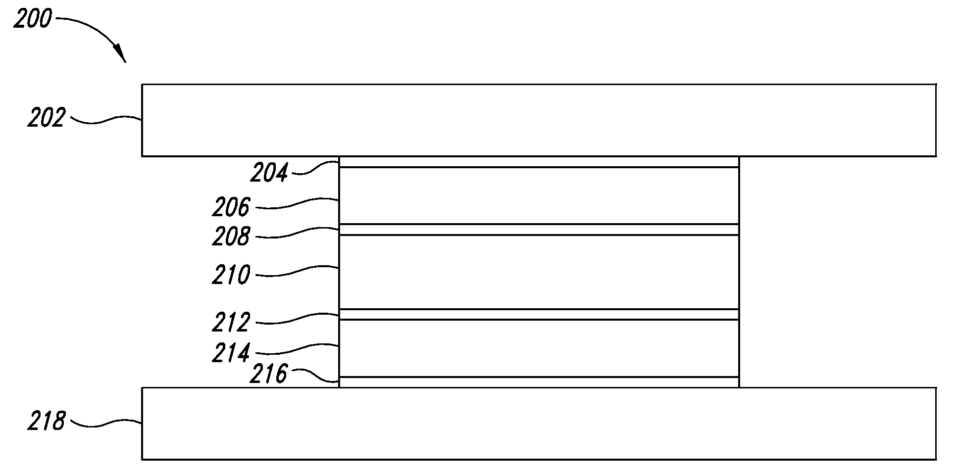
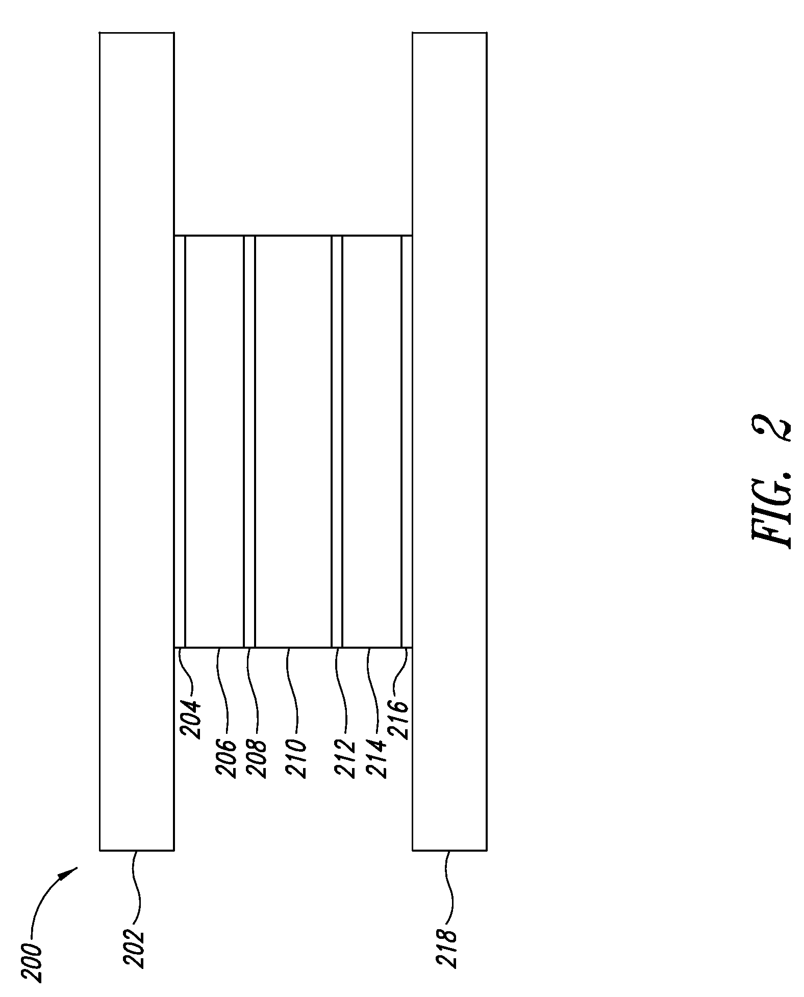
[0021]FIG. 2 illustrates a self-heating phase change memory (PCM) cell 200 in accordance with o...


PUM


Abstract

A method for manufacturing a phase change memory includes forming a phase change memory cell by forming a phase change layer between two switching layers. The phase change layer is separated from thermal heat sinks, such as the bitline or wordline, by the switching layers.

Description

BACKGROUND[0001]1. Technical Field[0002]The present disclosure relates generally to phase change memories.[0003]2. Description of the Related Art[0004]Phase change memory devices use phase change materials, i.e., materials that may be electrically switched between a generally amorphous and a generally crystalline state or between different detectable states of local order across the entire spectrum between completely amorphous and completely crystalline states, for electronic memory application. The state of the phase change materials is also non-volatile in that, when set in either a crystalline, semi-crystalline, amorphous, or semi-amorphous state representing a resistance value, that value is retained until changed by another programming event, as that value represents a phase or physical state of the material (e.g., crystalline or amorphous). The state is unaffected by removing electrical power.[0005]A phase change memory device includes an array of memory cells, each memory cel...

Claims


Application Information

Patent Timeline
IPC IPC(8): H01L47/00H01L21/00
CPCH01L27/2427H01L27/2463H01L45/06H01L45/1233H01L45/144H01L45/1666H10B63/24H10B63/80H10N70/231H10N70/826H10N70/8828H10N70/061
Inventor SAVRANSKY, SEMYON D.KARPOV, ILYA
Owner STMICROELECTRONICS SRL
Why Eureka
Try Eureka