Meter phase identification

a technology of phase identification and meter, applied in the direction of phase sequence/synchronization indication, frequency to phase shift conversion, instruments, etc., can solve the problems of incorrect information, incomplete or inaccurate records telling a smart meter b>16/b> installer which phase an individual customer b>6/b> is on, and the phase may become more heavily loaded than the other

Active Publication Date: 2010-07-01
ACLARA METERS LLC
View PDF15 Cites 24 Cited by
  • Summary
  • Abstract
  • Description
  • Claims
  • Application Information

AI Technical Summary

Problems solved by technology

However, as new customers are added over time, any one of the phases may become more heavily loaded than the others.
Consequently, the records telling a smart meter 16 installer which phase an individual customer 6 is on are incomplete or inaccurate.
This can be a very time-consuming and labor intensive process which can often lead to incorrect information.
During storms or emergencies this can also lead to safety issues as well.

Method used


Image

  • Meter phase identification
  • Meter phase identification
  • Meter phase identification

Examples


Embodiment Construction

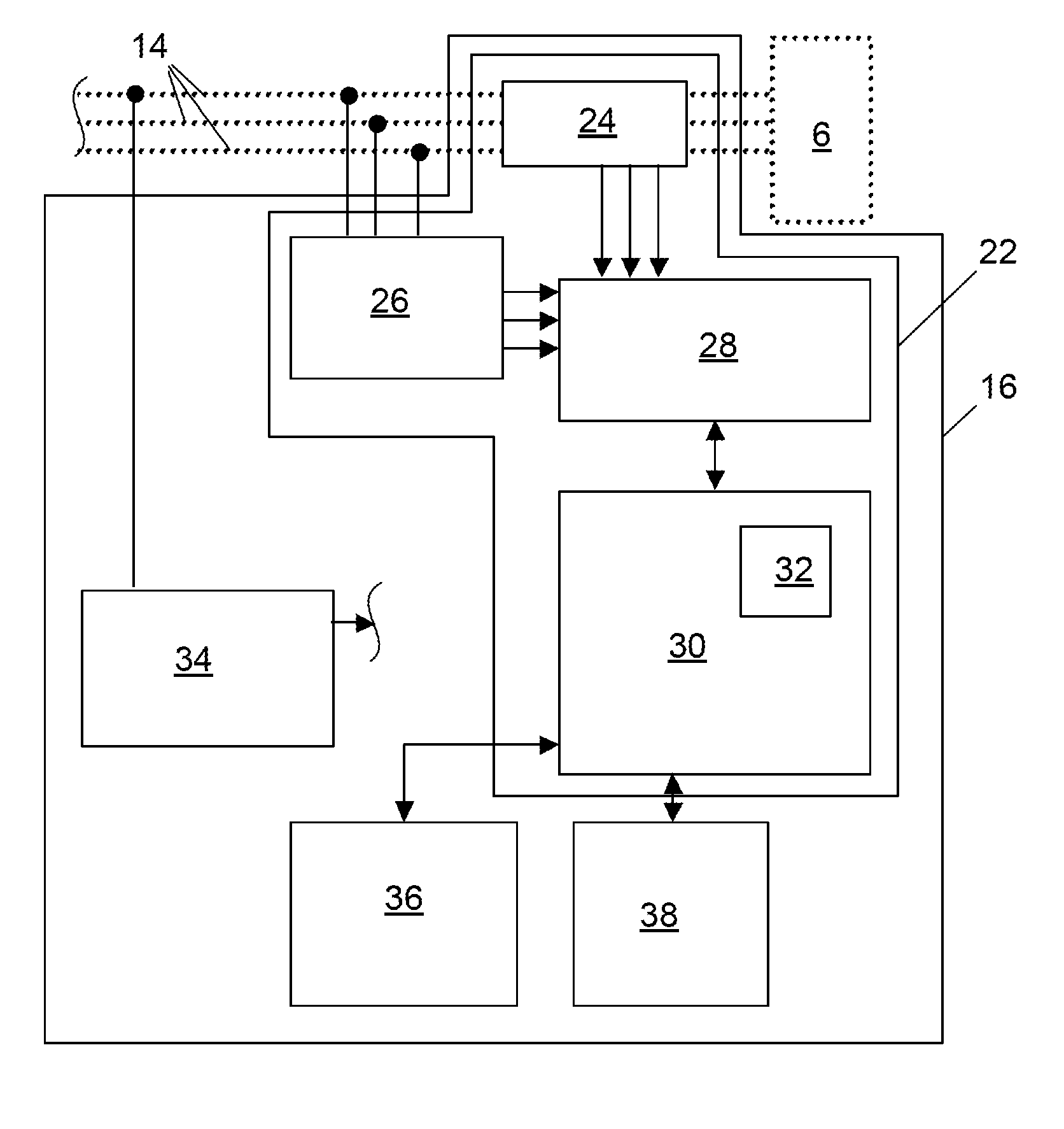
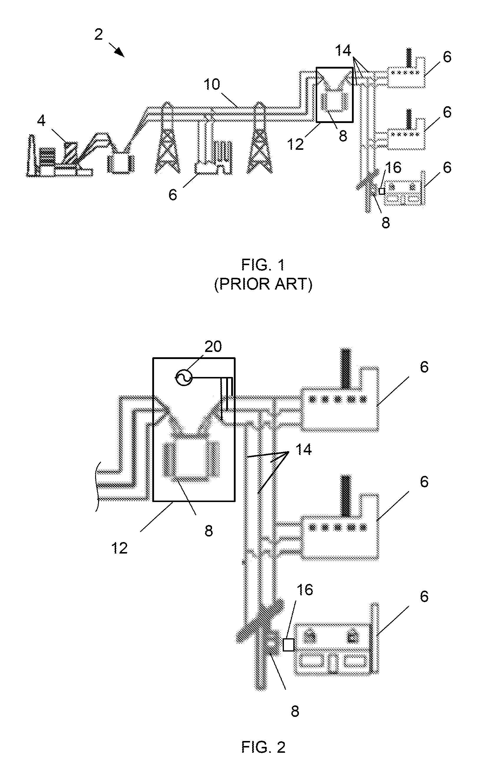
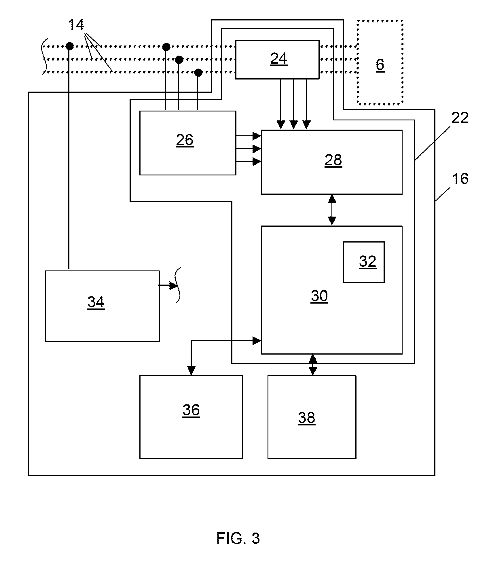
[0013]FIG. 2 illustrates multi-phase electrical power distribution network 2 including a substation 12, a signal generator 20 for providing a different signal on each of a plurality of phases leaving the substation 12. The signal generator 20 may be used with any power distribution network 2, including, but not limited to the network shown in FIG. 1. Although the signal generator 20 is illustrated as being arranged in the substation 12, the signal generator 20 may also be arranged at any location in the network 2 and / or may provide the signals at other points in the network such as at the generating plant 4 or transmission lines 10. The signals may also be provided on less than all of the phases and / or at different locations for any of the phases. Separate signal generators 20 may also be provided for each phase.

[0014]The signal generator(s) 20 provided signals which are capable of being distinguished from the typical 60 Hz or 50 Hz power signal provided on the power distribution ne...


PUM


Abstract

A multi-phase electrical power distribution network includes a substation; a signal generator for providing a different signal on each of a plurality of phases leaving the substation; and a signal discriminator for detecting each of the different signals at a consumer of the electrical power.

Description

BACKGROUND OF THE INVENTION[0001]1. Technical Field[0002]The subject matter described here generally relates to electricity measuring and testing, and, more particularly, to conductor identification or location including phase identification.[0003]2. Related Art[0004]As illustrated in FIG. 1, electric power distribution networks 2 are used by the electric utilities to deliver electricity from generating plants 4 to end-users, such as consumers or customers 6. Although the actual distribution voltages will vary from utility to utility, in the non-limiting example illustrated here, three-phase power from a generating plant 4 is fed to a generator step up transformer 8 which provides 765 V to 138 kV power to transmission lines 10. High voltage power from the transmission lines 10 is delivered to various substations 12 at which other transformers 8 step this voltage down to lower three-phase voltages and ultimately separate the power into three single-phase feeder lines 14. Each of thes...

Claims


Application Information

Patent Timeline
Patent Type & Authority Applications(United States)
IPC IPC(8): G01R25/00G01R19/00
CPCG01R29/18G01R31/023G01R31/60
Inventor CAIRD, KENNETH J.
Owner ACLARA METERS LLC
Why Eureka
Try Eureka