Rimless eyeglasses

a technology of eyeglasses and fixing parts, applied in the field of rimless eyeglasses, can solve the problems of looseness produced between the eyeglass lens and the lens fixing member, and difficulty in maintenance operations such as lens replacement, and achieve the effect of weak adhesive force and easy breakag

Inactive Publication Date: 2010-07-01
21TWO ONE
View PDF7 Cites 2 Cited by
  • Summary
  • Abstract
  • Description
  • Claims
  • Application Information

AI Technical Summary

Benefits of technology

[0012]With this structure, the cylindrical leg portion of the lens fixing portion of the eyeglass component is inserted into the lens hole formed in the eyeglass lens, whereby the lens fixing portion of the eyeglass component is fixedly attached to the eyeglass lens. At this stage, since the spiral-shaped groove is formed in the outer peripheral face of the leg portion, the inner peripheral face of the lens hole and the outer peripheral face of the leg portion come into approximately uniform contact with each other. As a result, loosening does not occur in the connecting area, and also the eyeglass component and the lens are easily attached or removed.
[0016]With this structure, since an adhesive can reliably fill the spiral-shaped groove, the adhesive runs evenly through the entire region of the connecting area between the inner peripheral face of the lens hole and the outer peripheral face of the leg portion, thus a reliable fixed attachment can be achieved. Accordingly, the leg portion is prevented from slipping out of the lens hole, and also backlash and play between them are not produced at all.
[0018]With this structure, since the contact between the inner peripheral face of the lens hole and the outer peripheral face of the leg portion is made on the flat face having a greater width, facial pressure on the eyeglass lens is reduced, making the occurrence of a fracture difficult. In addition, the adhesive also acts as a shock absorber, making it possible to further inhibit such occurrence of a fracture.
[0020]With this structure, because adhesives generally produce a weaker adhesive force between materials of different natures than that between materials of the same nature, the bond caused by the adhesive is easily broken without damage to the eyeglass lens by rotating the eyeglass lens and the lens fixing member relative to each other.

Problems solved by technology

However, such conventional eyeglasses undergo the problem of looseness produced between the eyeglass lens and the lens fixing member, for example, when the eyeglasses are continuously used for a long time, since the cylinder-shaped leg portion of the lens fixing member is simply inserted into a lens hole formed in the eyeglass lens in order to fix it to the eyeglass lens.
In this case, however, although the problem associated with the loosening is remedied, there is another problem of making maintenance operations such as lens replacement difficult.
In particular, when both the eyeglass lens and the lens fixing portion are formed of plastic, since the bonded portion is not easily separated, the only way to separate them is to break the eyeglass lens itself or the lens fixing portion itself, which is a significant problem.

Method used


Image

  • Rimless eyeglasses
  • Rimless eyeglasses
  • Rimless eyeglasses

Examples


first embodiment

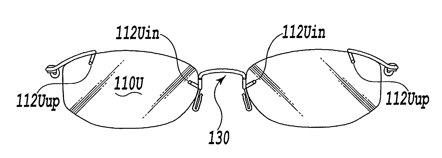
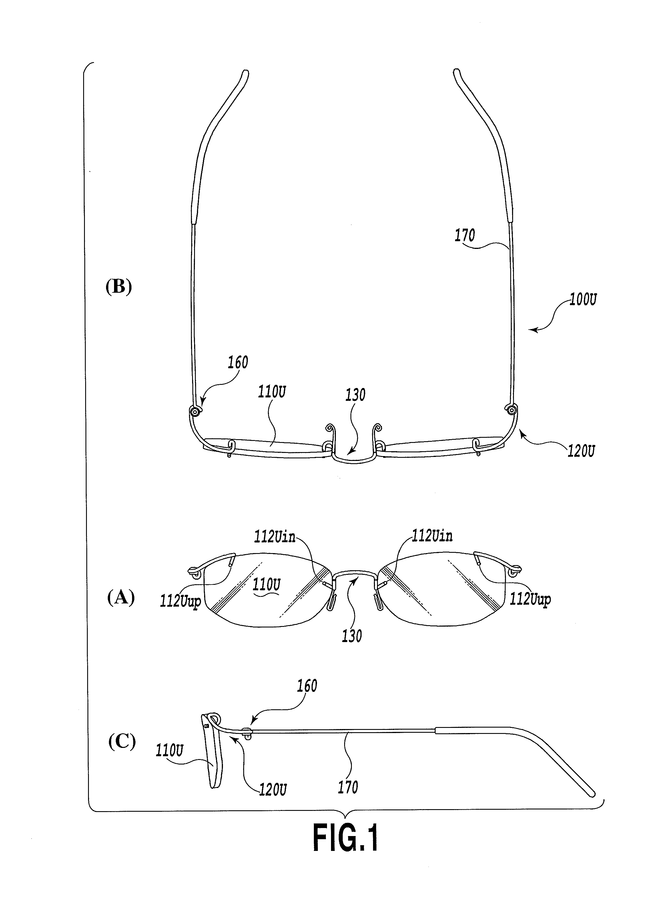
[0056]In the present invention, the rimless eyeglasses 100U are assembled and completed through the following procedure. First, each of the leg portions 132 of the metallic bridge member 130 is inserted from the back side of the lens 110U into the lens hole 112Uin perforated in the bridge-side portion of the lens 110U, and the leg portion 122U of the metallic end-piece member 120U is inserted from the back side of the lens 110U into the lens hole 112Uup perforated in end-piece-side portion of the lens 110U, in order to fixedly attach both the metallic bridge member 130 and the metallic end-piece member 120U to the lens 110U. It should be noted that, (A) of FIG. 5 shows by way of example how to insert the metallic end-piece member 120U. At this stage, regarding the metallic bridge member 130, the curvature of the U-shaped curved portion 135 and the perforation position of the bridge-side lens hole 112Uin are determined such that the lens hole 112Uin and the inner edge of the lens 110...

second embodiment

[0068]In the second embodiment, also, the outer peripheral faces of the leg portion 122S of the metallic end-piece member 120S and the leg portion 132 of the metallic bridge member 130 respectively have spiral-shaped grooves 128 and 138 formed therein, and flat faces 129 and 139 formed on the area between the turns of the spiral-shaped groove, which have a greater width B than the width A of the groove. Because of this, the inner peripheral face of the lens hole 112S and the outer peripheral face of each of the leg portions 122S and 132 come into approximately uniform contact with each other, and accordingly a fixed attachment between the lens 110S, the metallic end-piece member 120S and the metallic bridge member 130 is reliably established without producing loosening in the connecting areas between them. In addition, since the contact between the inner peripheral face of the lens hole 112S and the outer peripheral face of each of the leg portions 122S and 132 is achieved on the fl...


PUM


Abstract

Rimless eyeglasses are provided, which do not produce loosening in a connecting area between an eyeglass lens and a lens fixing portion, and which also allows for the easy attachment or removal of a lens. The rimless eyeglasses (100U) comprise eyeglass lenses (110U) and as eyeglass components, a metallic end-piece member (120U) and a metallic bridge member (130), having a lens fixing portion fixedly attached to the eyeglass lens and a connecting portion connected to a temple or a bridge. The lens fixing portions of the metallic end-piece member (120U) and the metallic bridge member (130) have cylindrical leg portions (122U) and (132) each inserted into a lens hole (112) formed in the eyeglass lens (110U). Spiral-shaped grooves (128) and (138) are formed in the outer peripheral faces of the leg portions. An adhesive is injected into the spiral-shaped grooves (128) and (138).

Description

TECHNICAL FIELD[0001]This invention relates to rimless eyeglasses having no rim, for holding the outer periphery of a lens.BACKGROUND ART[0002]Conventionally, such rimless glasses are known, for example as described in Patent Literature 1.[0003]Patent Literature 1 discloses rimless eyeglasses which comprise a lens fixing member which is fixedly attached to an eyeglass lens and a connecting member which is connected to a temple or to a bridge, to which the lens fixing member and the connecting member are detachably connected. The eyeglass lens and the lens fixing member are fixed in such a form that the cylinder-shaped leg portion of the lens fixing member, which is formed of a resin, is inserted into a lens hole formed in the lens.[0004]Also, Patent Literature 2 describes rimless eyeglasses which are designed such that a pair of right and left lenses are coupled and held by use of a metallic bridge, which has edge contact portions in parallel-line form capable of making linear conta...

Claims


Application Information

Patent Timeline
Patent Type & Authority Applications(United States)
IPC IPC(8): G02C1/02
CPCG02C1/02G02C5/008G02C5/2209G02C2200/10
Inventor HIRAMOTO, KIYOSHI
Owner 21TWO ONE
Why Eureka
Try Eureka