

Imaging lens
- Summary
- Abstract
- Description
- Claims
- Application Information
AI Technical Summary
Benefits of technology
Problems solved by technology
Method used
Image

Examples
embodiment 1
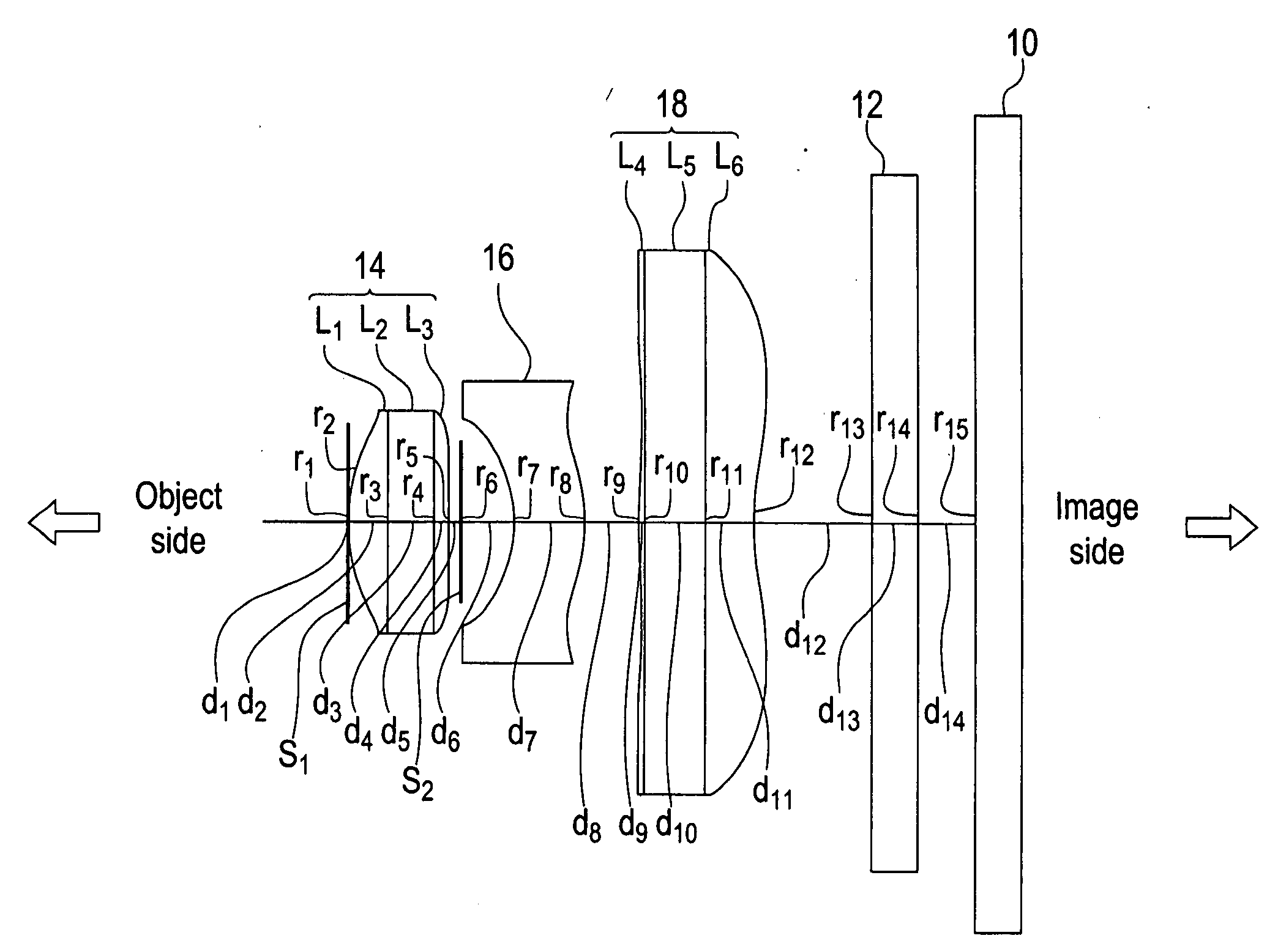
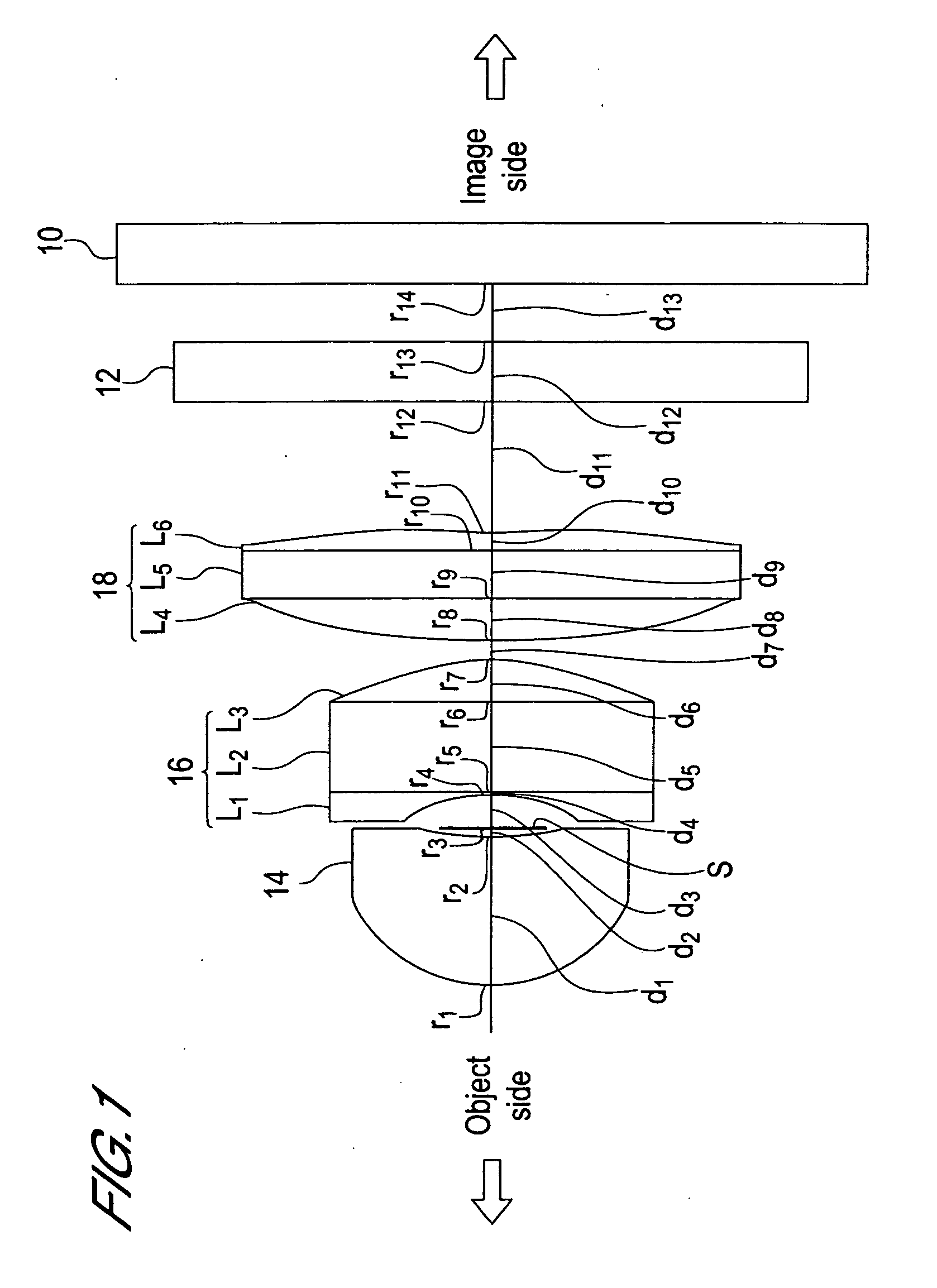
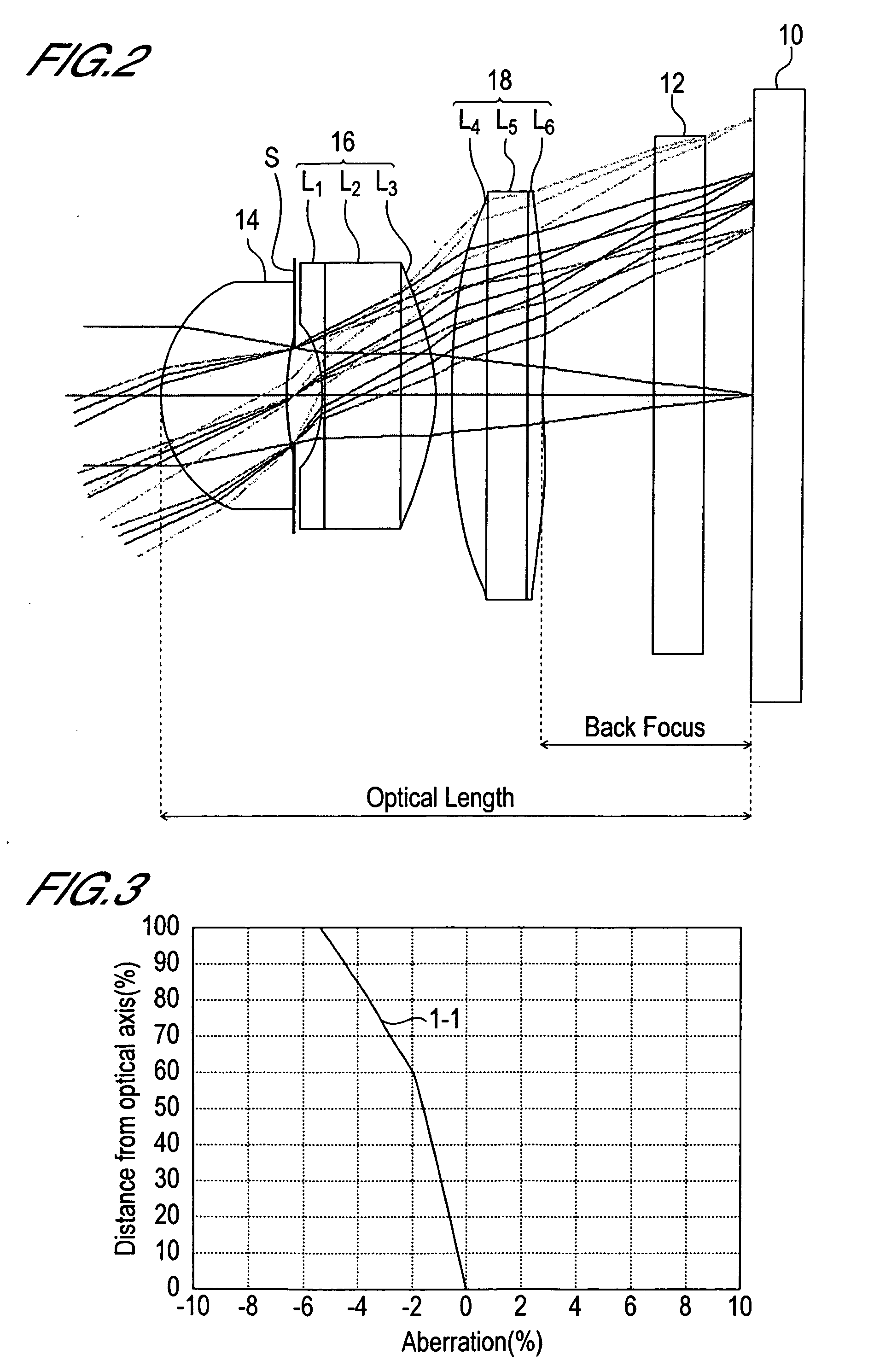
[0187]The imaging lens of Embodiment 1 is the imaging lens of the first aspect of the present invention and the embodiment of the first imaging lens, comprising a first lens 14, an aperture stop S, a second lens 16 and a third lens 18, where the first lens 14, the aperture stop S, the second lens 16 and the third lens 18 are arranged in this sequence from the object side to the image side, as shown in FIG. 1 and FIG. 2.
[0188]A single lens is used for the first lens 14. The second lens 16 is a junction type compound lens where a first sub-lens L1, a second sub-lens L2 and a third sub-lens L3 are arranged in this sequence from the object side to the image side, the first sub-lens L1 and the second sub-lens L2 are bonded, and the second sub-lens L2 and the third sub-lens L3 are bonded. The third lens 18 is a junction type compound lens where a fourth sub-lens L4 and a fifth sub-lens L5 and a sixth sub-lens L6 are arranged in this sequence from the object side to the image side, the fou...
embodiment 2
[0205]The imaging lens of Embodiment 2 is the imaging lens of the first aspect of the present invention and the embodiment of the second imaging lens, comprising an aperture stop (first diaphragm) S1, a first lens 14, a second, diaphragm S2, a second lens 16 and a third lens 18, where the aperture stop S1, the first lens 14, the second diaphragm S2, the second lens 16 and the third lens 18 are arranged in this sequence from the object side to the image side, as shown in FIG. 6 and FIG. 7.
[0206]A single lens is used for the second lens 16. The first lens 14 is a junction type compound lens where a first sub-lens L1, a second sub-lens L2 and a third sub-lens L3 are arranged in this sequence from the object side to the image side, the first sub-lens L1 and the second sub-lens L2 are bonded, and the second sub-lens L2 and the third sub-lens L3 are bonded. The third lens 18 is a junction type compound lens where a fourth sub-lens L4, a fifth sub-lens L5 and a sixth sub-lens L6 are arrang...
embodiment 3
[0224]The imaging lens of Embodiment 3 is an imaging lens of the first aspect of the present invention, and the embodiment of the third imaging lens of the present invention, comprising, an aperture stop (first diaphragm) S1, a first lens 14, a second diaphragm S2, a second lens 16 and a third lens 18, where the first diaphragm S1, the first lens 14, the second diaphragm S2, the second lens 16 and the third lens 18 are arranged in this sequence from the object side to the image side, as shown in FIG. 11 and FIG. 12.
[0225]A single lens is used for the third lens 18. The first lens 14 is a junction type compound lens where a first sub-lens L1, a second sub-lens L2 and a third sub-lens L3 are arranged in this sequence from the object side to the image side, the first sub-lens L1 and the second sub-lens L2 are bonded, and the second sub-lens L2 and the third sub-lens L3 are bonded. The second lens 16 is a junction type compound lens where a fourth sub-lens L4, a fifth sub-lens L5 and a ...
PUM
 Abstract
Description
Claims
Application Information