Channel change decision mechanism and method for a wireless network

a wireless network and channel change technology, applied in data switching networks, frequency-division multiplexes, instruments, etc., can solve problems such as complicated problems, reducing the usable bandwidth of channels, and affecting the selection of globally good channels. , to achieve the effect of improving the likelihood of selecting a globally good channel

Active Publication Date: 2010-07-01
SIGNIFY HLDG BV
View PDF6 Cites 52 Cited by
  • Summary
  • Abstract
  • Description
  • Claims
  • Application Information

AI Technical Summary

Benefits of technology

[0010]Patent application WO IB2007 / 050704 (Attorney Docket 005281), which is incorporated herein by reference, describes a mechanism for reporting when an interference problem has been detected, such that some node 120, typically PAN Coordinator 120a, would be able to select a better channel on which to operate wireless network 100. It also discloses the possibility that PAN Coordinator 120a, on receiving an interference report from some other node 120 in wireless network 100, would request further nodes 120 to carry out an assessment of the local channel conditions, and report these back, further improving the likelihood of selecting a globally “good” channel.

Problems solved by technology

Other devices (e.g., so-called “WiFi” devices) also operate in the 2.4 GHz band, and WiFi traffic can interfere with ZigBee traffic.
The problem that PAN Coordinator 120a has then is how to decide on what it should base its decision as to what to do with the information.
However, this problem is complicated by the nature of interferers to wireless network 100.
Some interferers completely block out transmission on a channel, but many other interferers may just reduce the usable bandwidth of the channel.
Given that in many cases it is not possible to have all nodes 120 running in an environment completely free of any interference, a problem arises as to what the “optimal” situation is that PAN Coordinator 120a should try to achieve, and on what criteria it should base its trade-off decisions.

Method used


Image

  • Channel change decision mechanism and method for a wireless network
  • Channel change decision mechanism and method for a wireless network
  • Channel change decision mechanism and method for a wireless network

Examples


Embodiment Construction

[0024]The present invention will now be described more fully hereinafter with reference to the accompanying drawing figures, in which preferred embodiments of the invention are shown. This invention may, however, be embodied in different forms and should not be construed as limited to the embodiments set forth herein. Rather, these embodiments are provided as teaching examples of the invention.

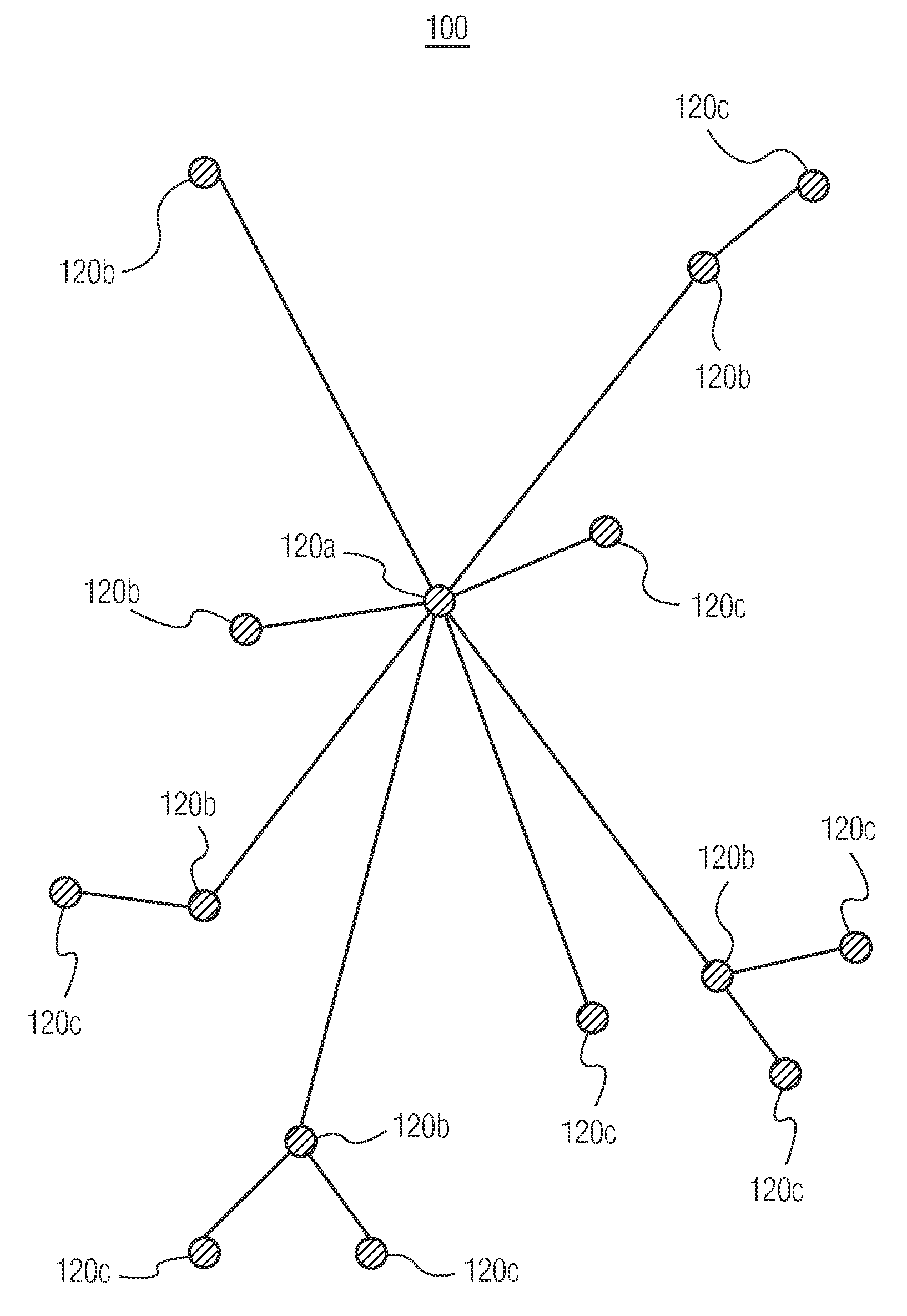
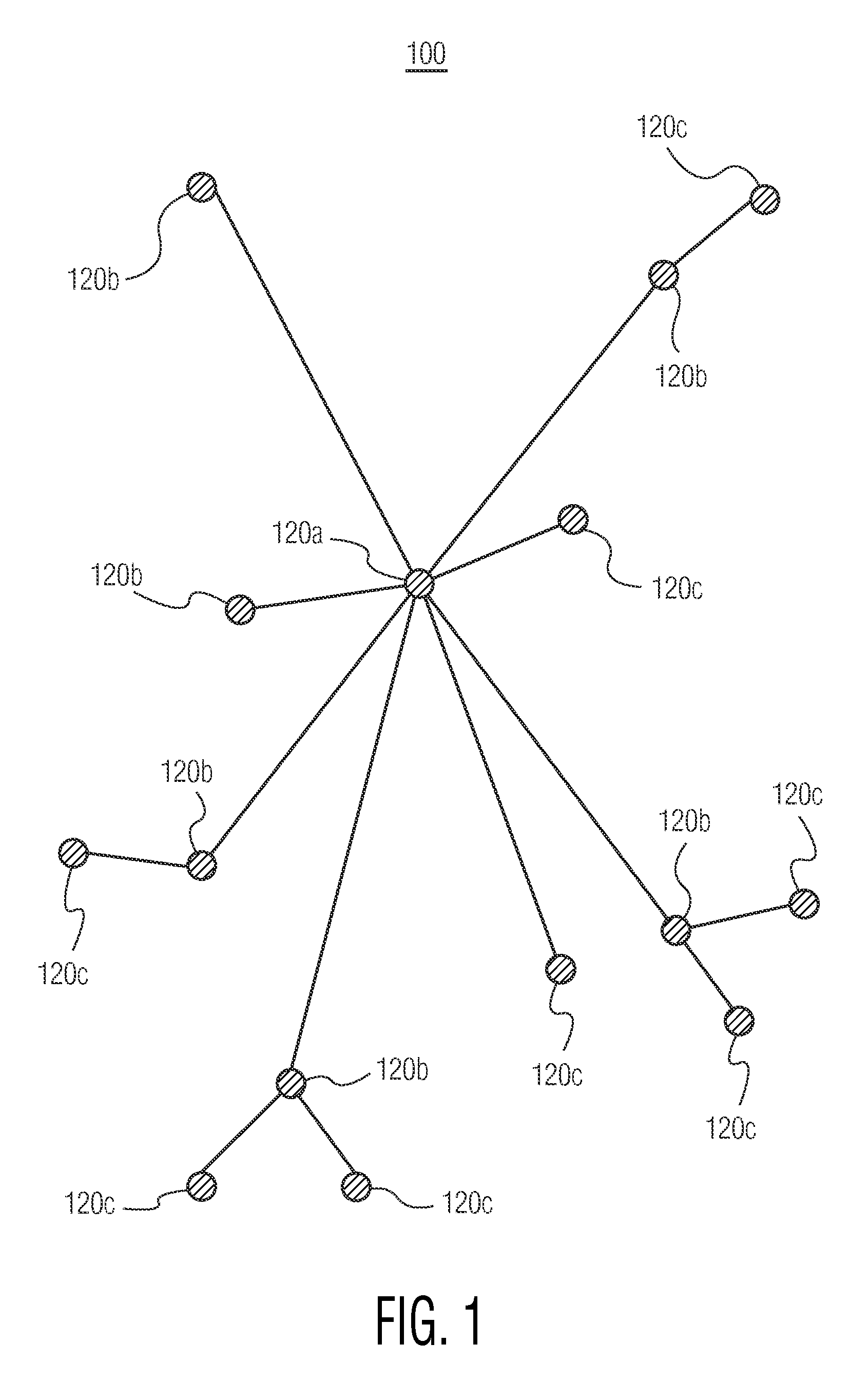
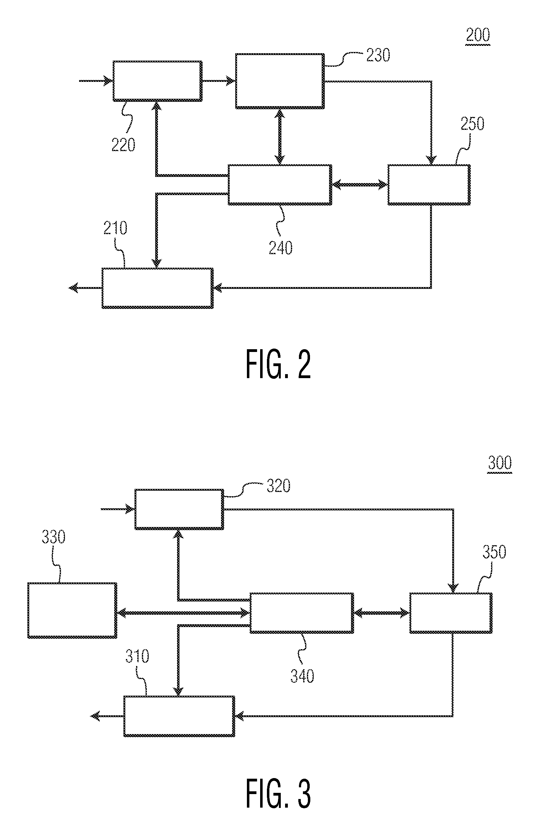
[0025]FIG. 2 shows a functional diagram of one embodiment of a wireless device 200, which may be employed as a wireless device 120 in wireless network 100 of FIG. 1. As will be appreciated by those skilled in the art, one or more of the various “parts” shown in FIG. 2 may be physically implemented using a software-controlled microprocessor, hard-wired logic circuits, or a combination thereof. Also, while the parts are functionally segregated in FIG. 2 for explanation purposes, they may be combined variously in any physical implementation.

[0026]Wireless device 200 includes transmitter 210, rece...


PUM


Abstract

In a communication network (100) comprising a plurality of wireless devices (120), a method determines whether to change one or more communication channels over which the wireless devices (120) communicate. The method includes receiving a plurality of configuration parameters for the communication network (100); receiving information related to one or more communication channel's availability for communications by one or more of the wireless devices (120); and determining whether to change one or more communication channels over which the wireless devices (120) communicate by executing a communication channel change determination algorithm using the configuration parameters and the received information related to one or more communication channel's availability for communications by one or more of the wireless devices (120).

Description

TECHNICAL FIELD[0001]This invention pertains to wireless devices and wireless networks, and more specifically to gathering data about the conditions of communication channels for a wireless device, and reporting the data to a wireless network.BACKGROUND AND SUMMARY[0002]Wireless networks are increasingly commonly employed to provide enhanced capabilities for a variety of devices. One category of wireless networks is a wireless Personal Area Network (PAN). One suitable format for communications in a wireless PAN is described by the ZigBee Specification for low cost, low power wireless radio links, as defined by the ZigBee Alliance. ZigBee wireless PANs are especially suitable for use, for example, in home automation networks for controlling lights, security systems, fire alarms, heating-ventilation-and-air-conditioning (HVAC) systems, etc.[0003]FIG. 1 shows one exemplary embodiment of a wireless network 100 including a plurality of wireless devices 120. Wireless network 100 may be a ...

Claims


Application Information

Patent Timeline
Patent Type & Authority Applications(United States)
IPC IPC(8): H04W72/12H04L12/26H04W36/14H04W36/30
CPCH04W36/26H04W36/30H04W24/02H04W88/18
Inventor RRDLAND, PHILIP ANDREWBENJES, IMMO
Owner SIGNIFY HLDG BV
Why Eureka
Try Eureka