
System and method for automatic construction of realistic looking tooth roots

a technology of automatic construction and tooth roots, applied in the field of dental and/or orthodontic treatment, can solve the problems of many impression techniques that do not capture or use corresponding root information, limit the ability of the complete tooth model to facilitate orthodontic treatment, and many impression techniques that do not capture or use root information

Inactive Publication Date: 2010-07-01
ALIGN TECH
View PDF2 Cites 51 Cited by
  • Summary
  • Abstract
  • Description
  • Claims
  • Application Information

AI Technical Summary

Benefits of technology

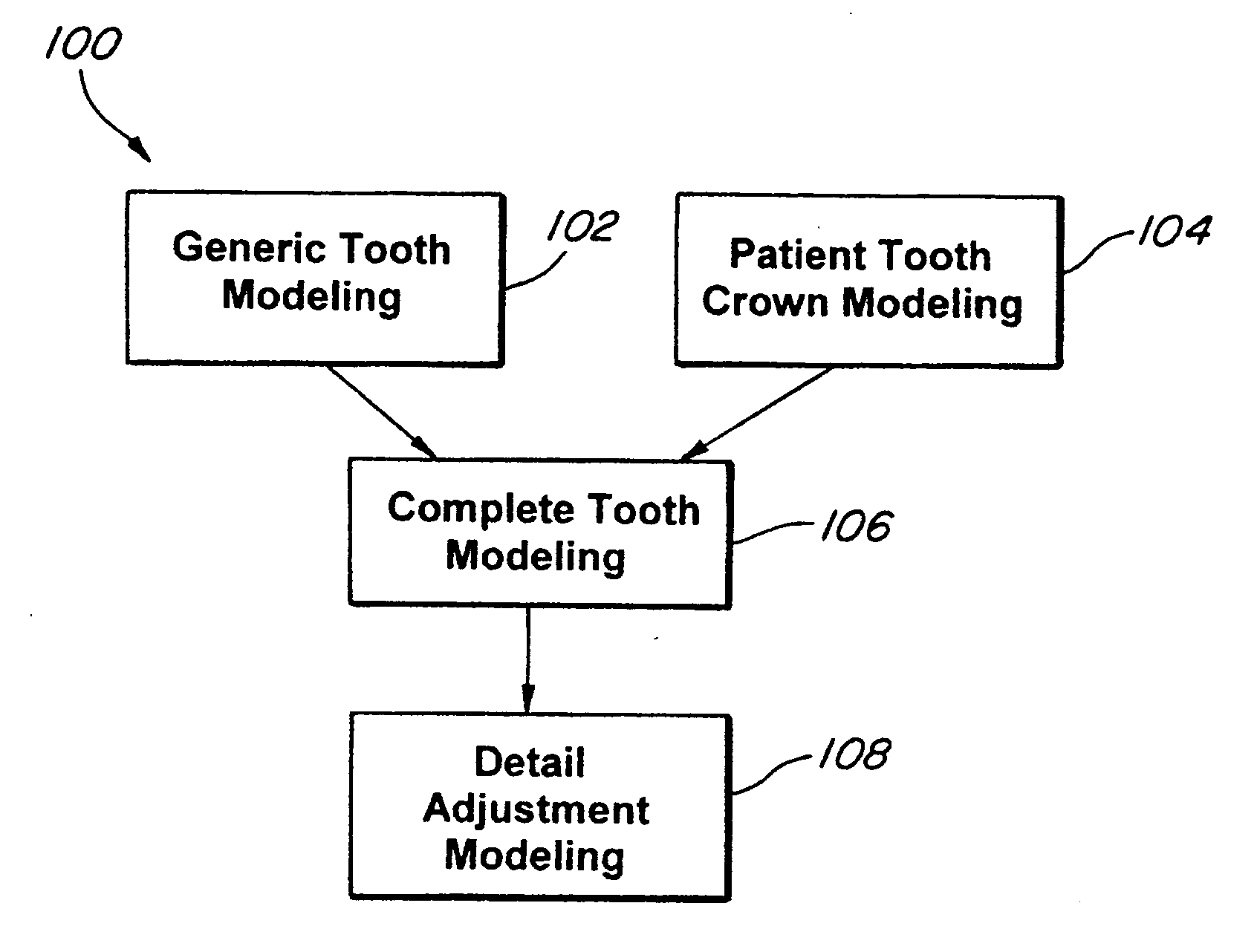
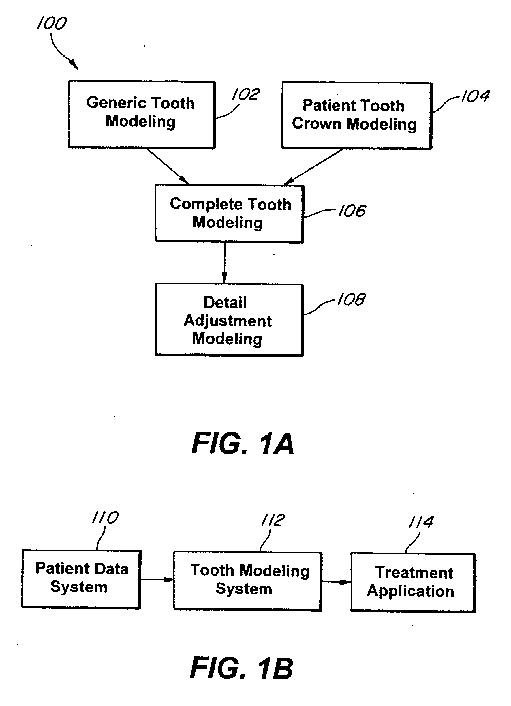
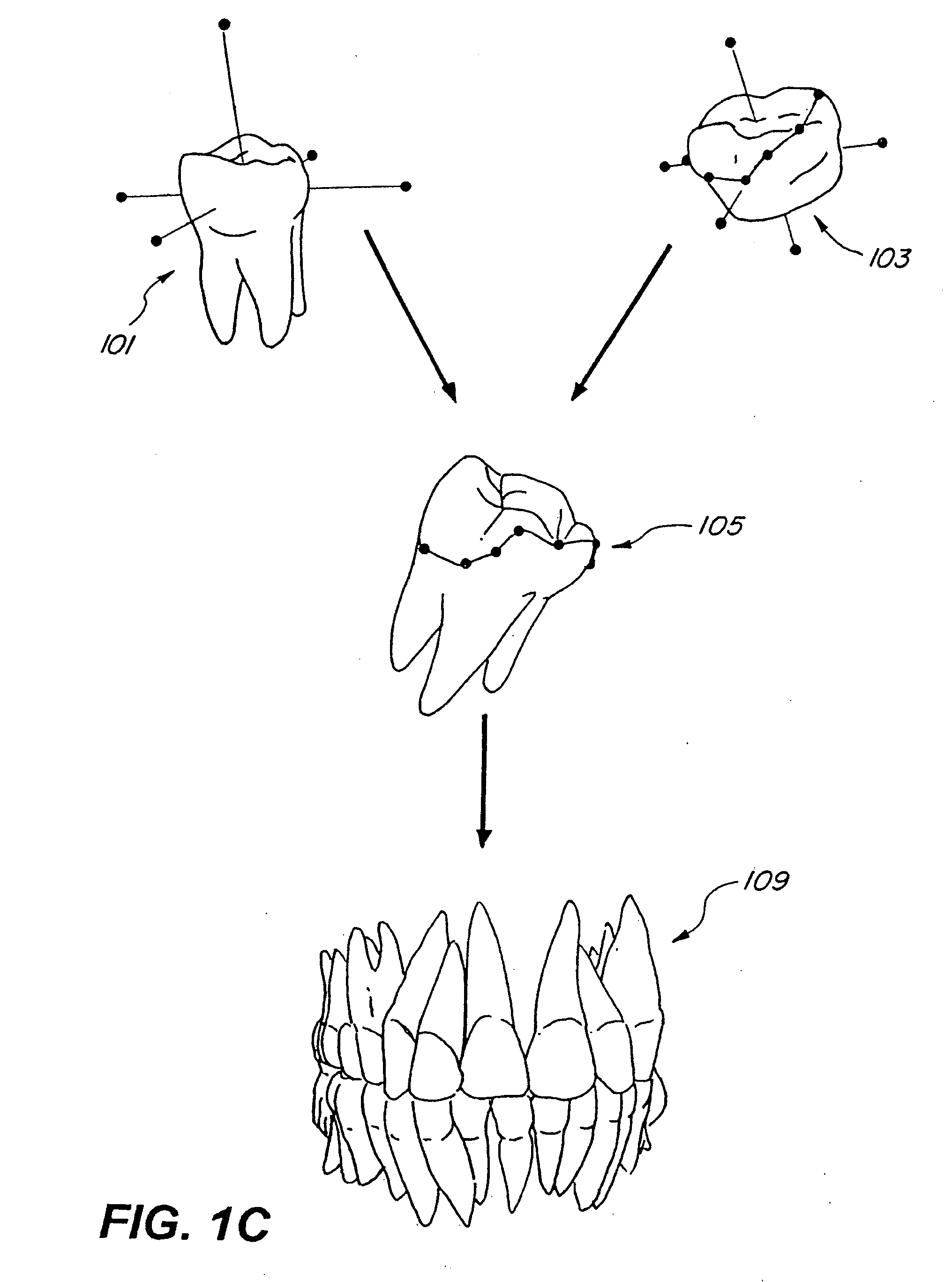
[0007]Such a process may be suitably applied for any and all of the various teeth within a patient, such as molars, bicuspids, canines or any other teeth within a patient. Various exemplary embodiments may comprise methods and systems for automated generation of morphing landmarks, model segmentation, root and crown stitching and / or three-dimensional root model adjustment. Such modeling techniques may be conducted with one or more computer-based systems, such as systems configured for storing actual patient data and generic tooth data, morphing generic tooth data to such patient's data and / or facilitating additional orthodontic treatment applications, through the use of one or more algorithms.

Problems solved by technology

Many techniques for impression-based computational orthodontics are limited to crown modeling of the patient's tooth, such as the capturing of crown and gum shape information.
Many impression techniques do not capture or use corresponding root information.
As a result, such impression techniques do not provide for the root component within the present tooth model, and often fail to account for root movement and / or interaction within the gums, thus limiting the ability of the complete tooth model in facilitating orthodontic treatment.
Such failure to account for root movement can also result in root collision that hinders the orthodontic treatment process.

Method used


Image

  • System and method for automatic construction of realistic looking tooth roots
  • System and method for automatic construction of realistic looking tooth roots
  • System and method for automatic construction of realistic looking tooth roots

Examples


Embodiment Construction

[0024]The present invention may be described herein in terms of various components and processing steps. It should be appreciated that such components and steps may be realized by any number of hardware and software components configured to perform the specified functions. For example, the present invention may employ various electronic control devices, visual display devices, input terminals and the like, which may carry out a variety of functions under the control of one or more control systems, microprocessors or other control devices.

[0025]In addition, the present invention may be practiced in any number of orthodontic or dental contexts and the exemplary embodiments relating to a system and method for modeling of complete tooth of a patient as described herein are merely a few of the exemplary applications for the invention. For example, the principles, features and methods discussed may be applied to any orthodontic or dental treatment application or process.

[0026]For illustra...


PUM


Abstract

A system and computer-implemented method including generating a patient digital tooth model including a crown component; generating landmarks on an edge of the crown component; and generating a generic digital tooth model corresponding to the patient digital tooth model. The generic digital tooth model including both root and crown components. The method also includes mapping the landmarks on the edge of the crown component on to the generic digital tooth model; solving a first morphing function to fix landmarks on an edge of the crown component to a ring-edge space; solving a second morphing function to fix landmarks on the generic digital tooth model to ring-edge space; and selecting vertices in ring-edge space to stitch tooth crown with morphed template root.

Description

BACKGROUND[0001]1. Field of the Invention[0002]The present invention relates, generally, to dental and / or orthodontic treatment, and in particular to a system and method for modeling realistic looking tooth roots of a patient to facilitate dental and / or orthodontic treatment.[0003]2. Related Art[0004]The ability to provide an accurate and complete modeling of teeth is an important element in the growing field of computational orthodontics and other computer aided dental treatment systems. Many techniques for impression-based computational orthodontics are limited to crown modeling of the patient's tooth, such as the capturing of crown and gum shape information. Many impression techniques do not capture or use corresponding root information. As a result, such impression techniques do not provide for the root component within the present tooth model, and often fail to account for root movement and / or interaction within the gums, thus limiting the ability of the complete tooth model in...

Claims


Application Information

Patent Timeline
IPC IPC(8): A61C5/02
CPCA61C7/00A61C7/002
Inventor SPIRIDONOV, ANTONPIMENOV, ALEXANDER
Owner ALIGN TECH
Learn More