Retrograde cutter with rotating blade

a cutter and rotating blade technology, applied in the field of retrograde cutters with rotating blades, can solve problems such as limitations on cutting instruments

Active Publication Date: 2010-07-01
ARTHREX
View PDF13 Cites 38 Cited by
  • Summary
  • Abstract
  • Description
  • Claims
  • Application Information

AI Technical Summary

Benefits of technology

[0009]These and other features and advantages of the invention will be more apparent from the following detailed descr...

Problems solved by technology

Surgical instruments inserted through cannulas must be long and thin—this presents limitations on instru...

Method used


Image

  • Retrograde cutter with rotating blade
  • Retrograde cutter with rotating blade
  • Retrograde cutter with rotating blade

Examples


Embodiment Construction

[0018]The following description is provided to enable any person skilled in the art to make and use the invention and sets forth the best modes contemplated by the inventors of carrying out their invention. Various modifications, however, will remain readily apparent to those skilled in the art.

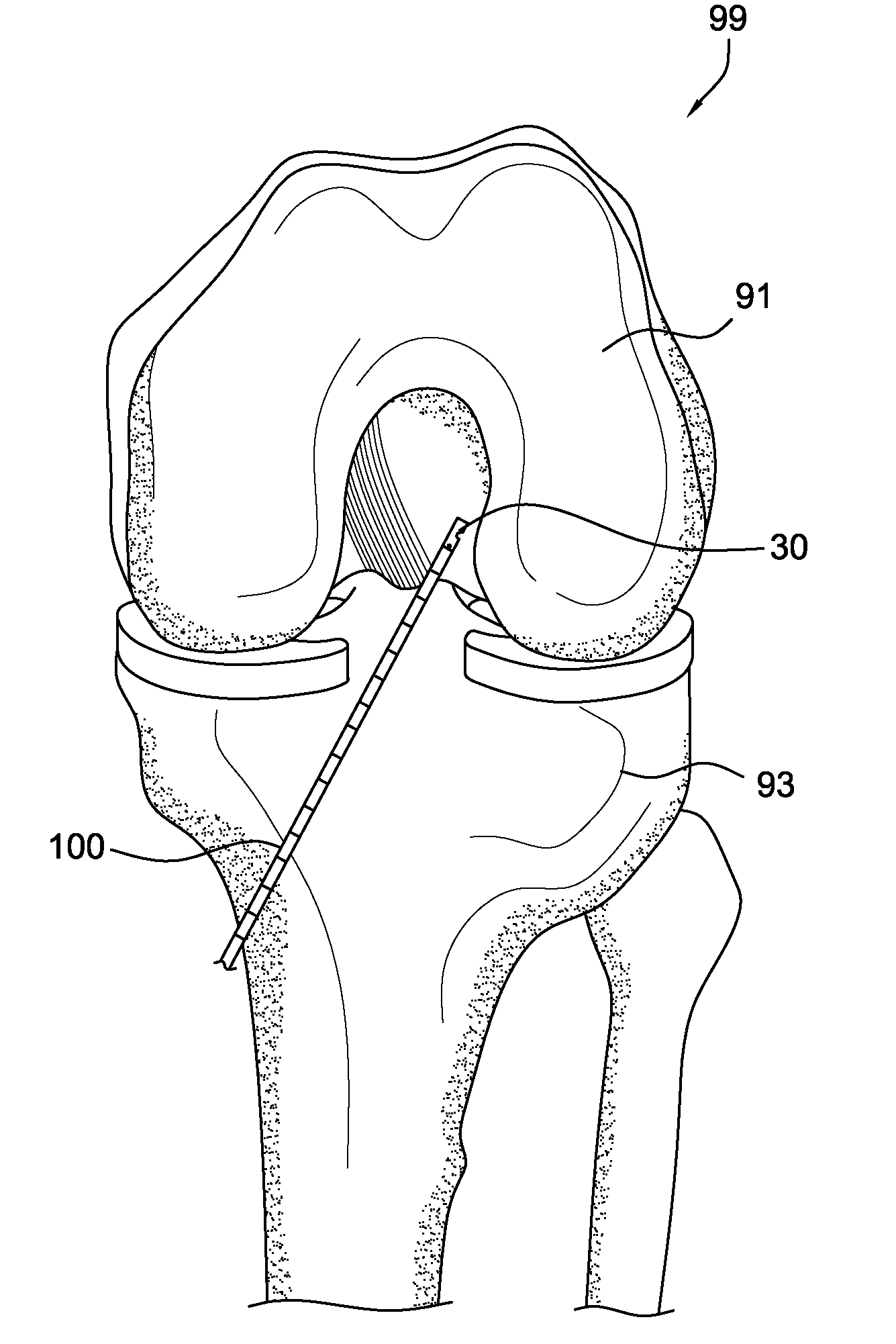
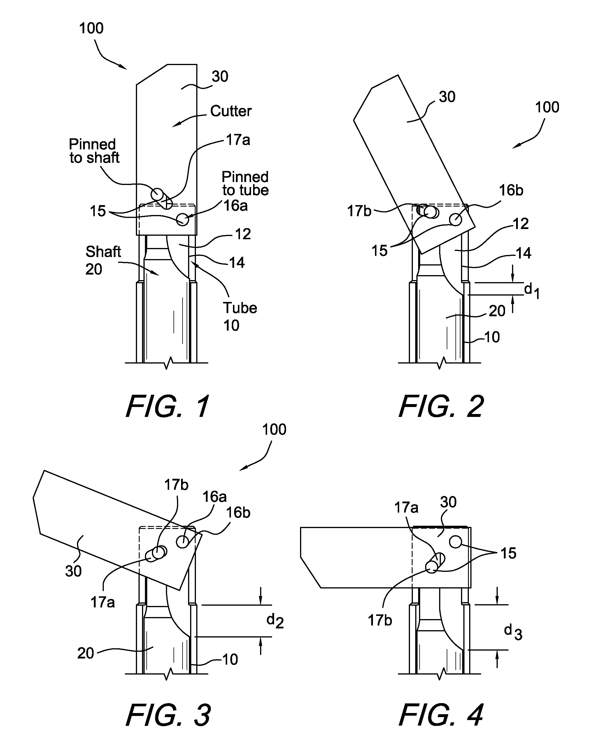
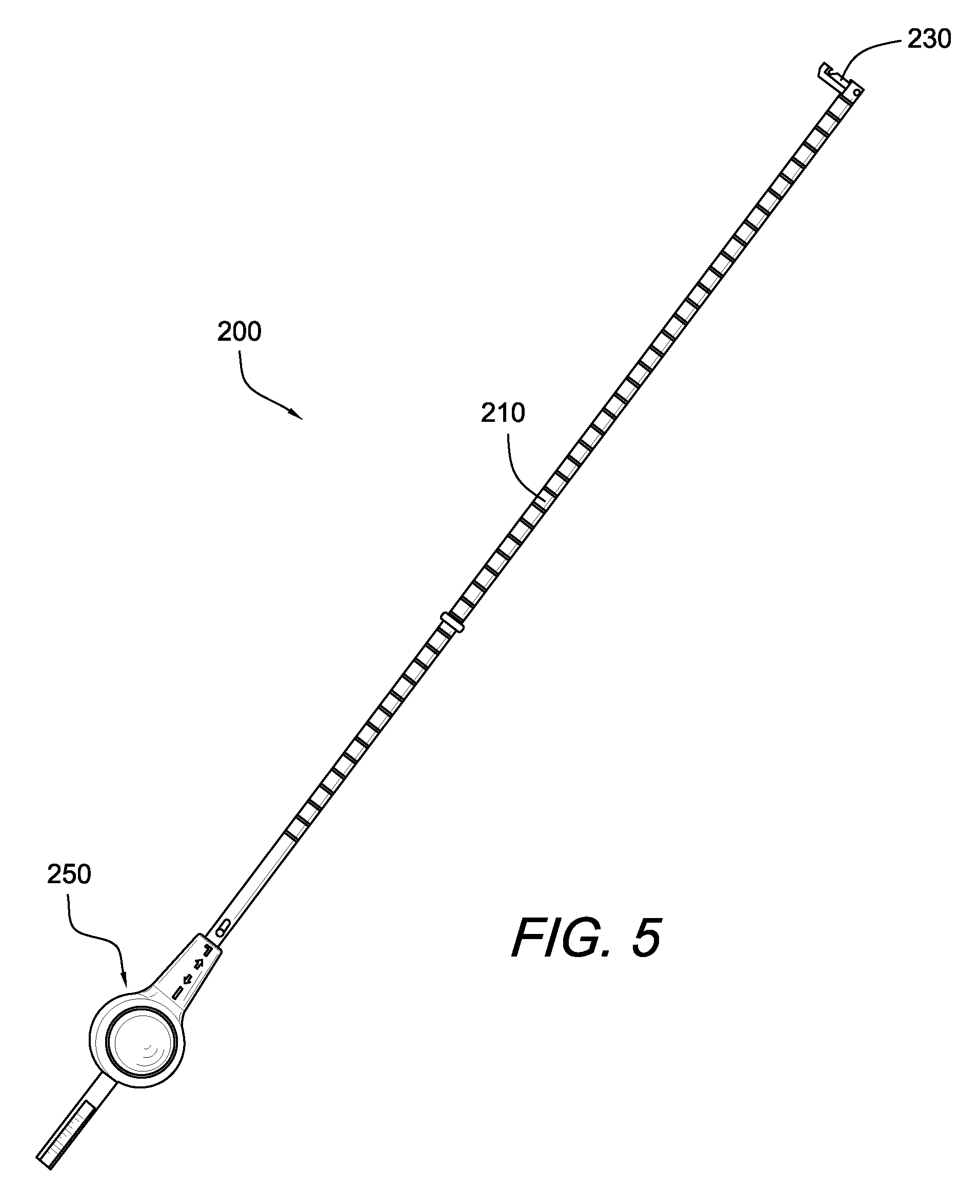
[0019]The present invention provides a flip cutter instrument that is designed to automatically convert linear movement of the shaft of the instrument into a rotational movement of the cutter tip (blade) of the instrument. The flip cutter instrument is provided with a mechanism (such as a pin and a slot, for example) that converts linear motion into rotational motion and locks the blade into position. The cutting blade is configured to engage the shaft of the instrument and to lock into the shaft. The blade is articulated between at least a first “straight” position (for example, about parallel to the longitudinal axis of the instrument) and at least a second “flip” position (for example, a n...


PUM


Abstract

A cutting instrument having a body, a blade at a distal end of the body, and a mechanism for rotating the blade from a first to a second position. The instrument can be used in a method of retrograde drilling a hole in bone. The cutting instrument is provided with a mechanism (for example, a pin and a slot) that converts linear motion into rotational motion and locks the blade into position. The cutting blade is configured to engage the shaft of the instrument and to lock into the shaft. The cutting blade is articulated between at least a first “straight” position (for example, about parallel to the longitudinal axis of the instrument) when the instrument cuts in an antegrade manner, and at least a second “flip” position (for example, a non-parallel position relative to the longitudinal axis of the instrument) when the instrument cuts in a retrograde manner. The cutting blade may be provided with a suture passing notch. The cutter instrument may also include a button mechanism for controlling the linear movement.

Description

CROSS-REFERENCE TO RELATED APPLICATIONS[0001]This application claims the benefit of U.S. Provisional Application No. 61 / 141,183 entitled “MECHANISM FOR CONVERTING LINEAR MOVEMENT INTO ROTATIONAL MOVEMENT FOR SURGICAL INSTRUMENT,” filed on Dec. 29, 2008, the entire disclosure of which is incorporated by reference herein. This application is also a continuation-in-part of U.S. application Ser. No. 12 / 114,599 (published as U.S. Publ. No. 2009 / 0275950 A1), filed May 2, 2008, which claims priority to U.S. Provisional Application No. 60 / 915,607, filed on May 2, 2007, the entire disclosures of which are hereby incorporated by reference.FIELD OF THE INVENTION[0002]The present invention relates to a mechanism for converting linear movement into rotational movement for a surgical instrument, such as a flip retrograde cutting instrument.BACKGROUND OF THE INVENTION[0003]During arthroscopic surgery, a small incision is made in the skin covering the arthroscopic site or joint, and a cannula is in...

Claims


Application Information

Patent Timeline
IPC IPC(8): A61B17/00
CPCA61B17/1617A61B17/1675A61B17/1714A61B2090/062
Inventor SHERMAN, GARY SCOTT
Owner ARTHREX
Why Eureka
Try Eureka