Expandable body cavity liner device

a vascular cavity and expandable technology, applied in the field of vascular cavity liners and vascular cavity neck bridges, can solve the problems of increased internal pressure, increased risk of overfilling of the sac, and consequent migration of embolic agents into the parent vessel, and achieves low internal pressure, low elasticity, and low yield strength

Inactive Publication Date: 2010-07-01
STRYKER EURO OPERATIONS HLDG LLC
View PDF50 Cites 29 Cited by
  • Summary
  • Abstract
  • Description
  • Claims
  • Application Information

AI Technical Summary

Problems solved by technology

At present, the treatment of aneurysms with drugs is substantially ineffective.
For example, there is a risk of overfilling the sac and consequent embolic agent migration into the parent vessel.
Overfilling of the sac also generates additional pressure in the aneurysm.
Deploying the balloon within the aneurysm can be rather difficult due to the high rates of blood flow through the aneurysm.
Elastic balloons have exhibited problems with respect to performance and have not been used endovascularly in some time.
This aneurysm filling technique also has its problems.
As the balloon is filled, the operator must be very careful not to overfill the balloon due to possible risk of rupturing the aneurysm.
Accordingly, the balloon may be too small, potentially resulting in the release of the balloon from the aneurysm into the blood stream.
Furthermore, the balloon often does not mold or shape to the odd-shaped contours of the aneurysm leaving room for blood to continue flowing through the aneurysm, or generating undesired pressure on the aneurysm wall.
For example, while the aneurysm liner concept is intuitively attractive, it has posed a number of technical challenges.
One primary challenge involves the difficulty in producing a material that is robust enough to contain embolic material without inhibiting the ability of the embolics to conform to the aneurysm geometry itself, rather than the geometry of the liner.
For example, the elastic materials discussed above generally require to much force to deform, and inelastic materials that deform readily do not have adequate memory to conform to the aneurysmal wall.
Different types of aneurysms also present different challenges.
For example, aneurysms which have a particularly wide opening between the aneurysm sac and the parent vessel (“wide neck aneurysms”) present difficulties concerning the retention of embolic materials.
Specifically, wide neck aneurysms make if very difficult to maintain the embolics, or occlusive materials, within the aneurysmal sac.
Of course, should the embolic material enter the parent vessel, it poses an undesirable risk of occlusion in the parent vessel.
Some current aneurysm liner concepts are inadequate in treating larger aneurysms.
However, these mesh materials are difficult to use in treating aneurysms larger than, for example, twelve millimeters in diameter.
Such mesh materials result in an assembly which is too bulky when collapsed down onto the catheter for delivery.
In other words, the amount of materials required to fill a relatively large aneurysm is very difficult to collapse down into a constrained, low profile, delivery configuration small enough to be delivered and deployed without excess friction on the walls of the delivery catheter or other delivery lumen.

Method used


Image

  • Expandable body cavity liner device
  • Expandable body cavity liner device
  • Expandable body cavity liner device

Examples


Embodiment Construction

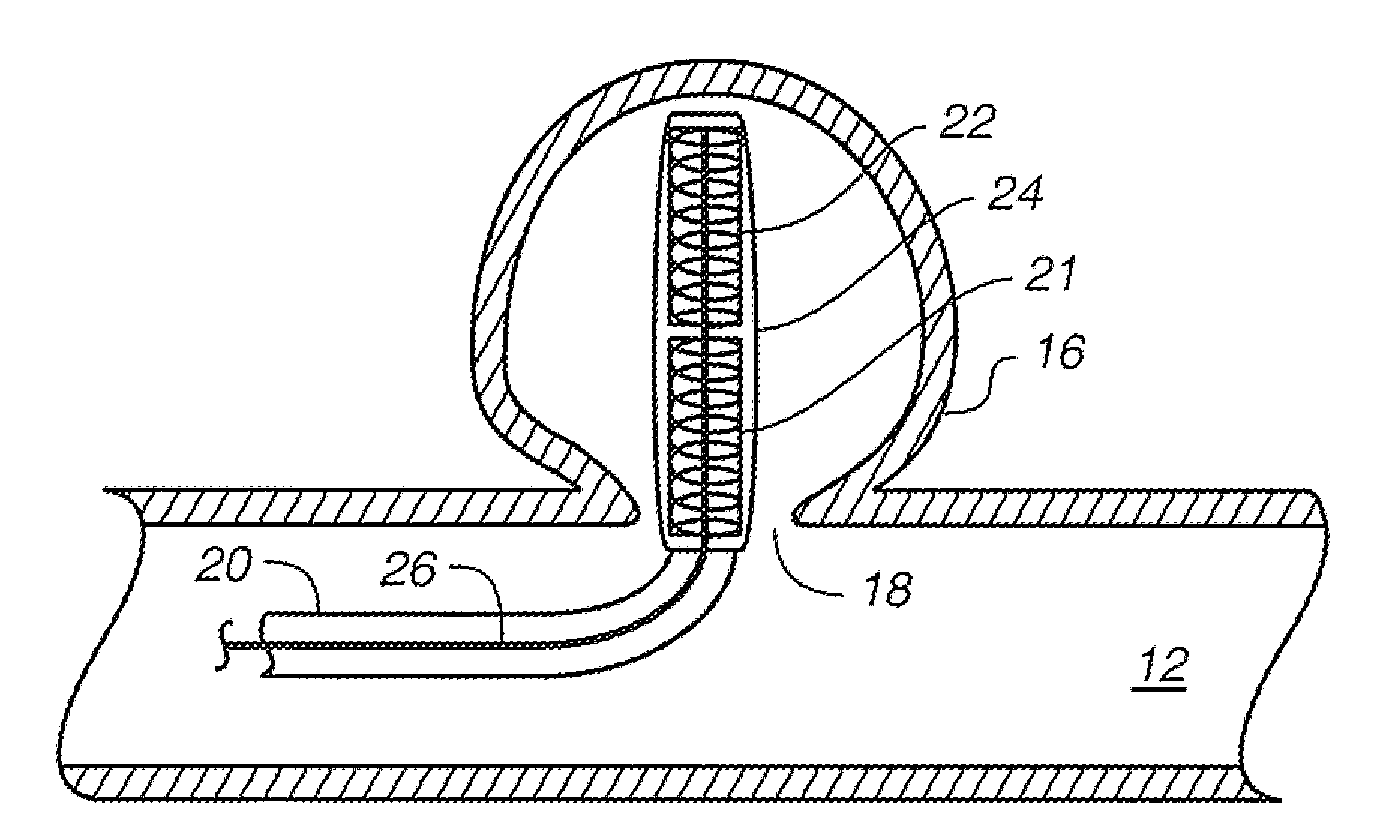
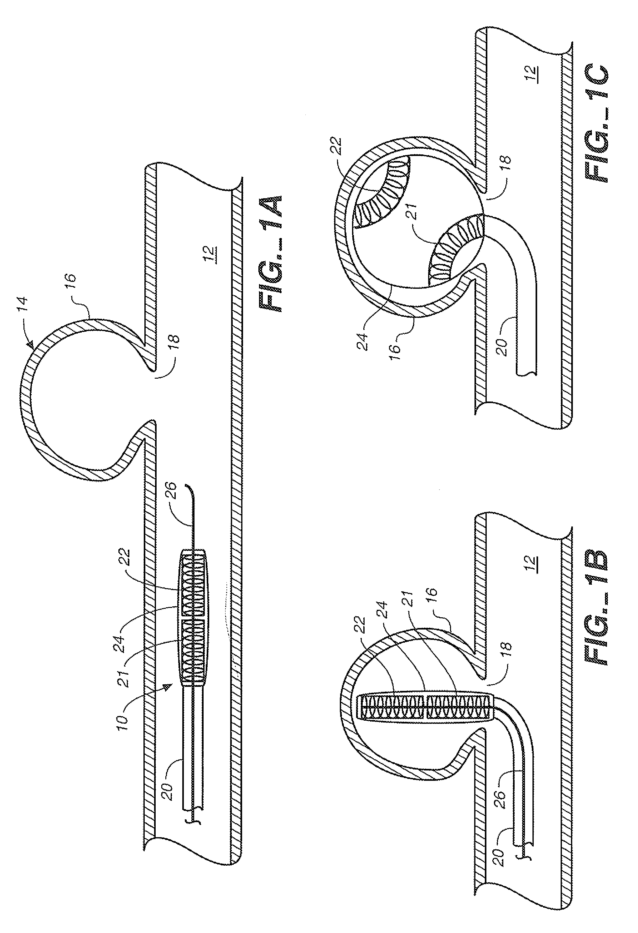
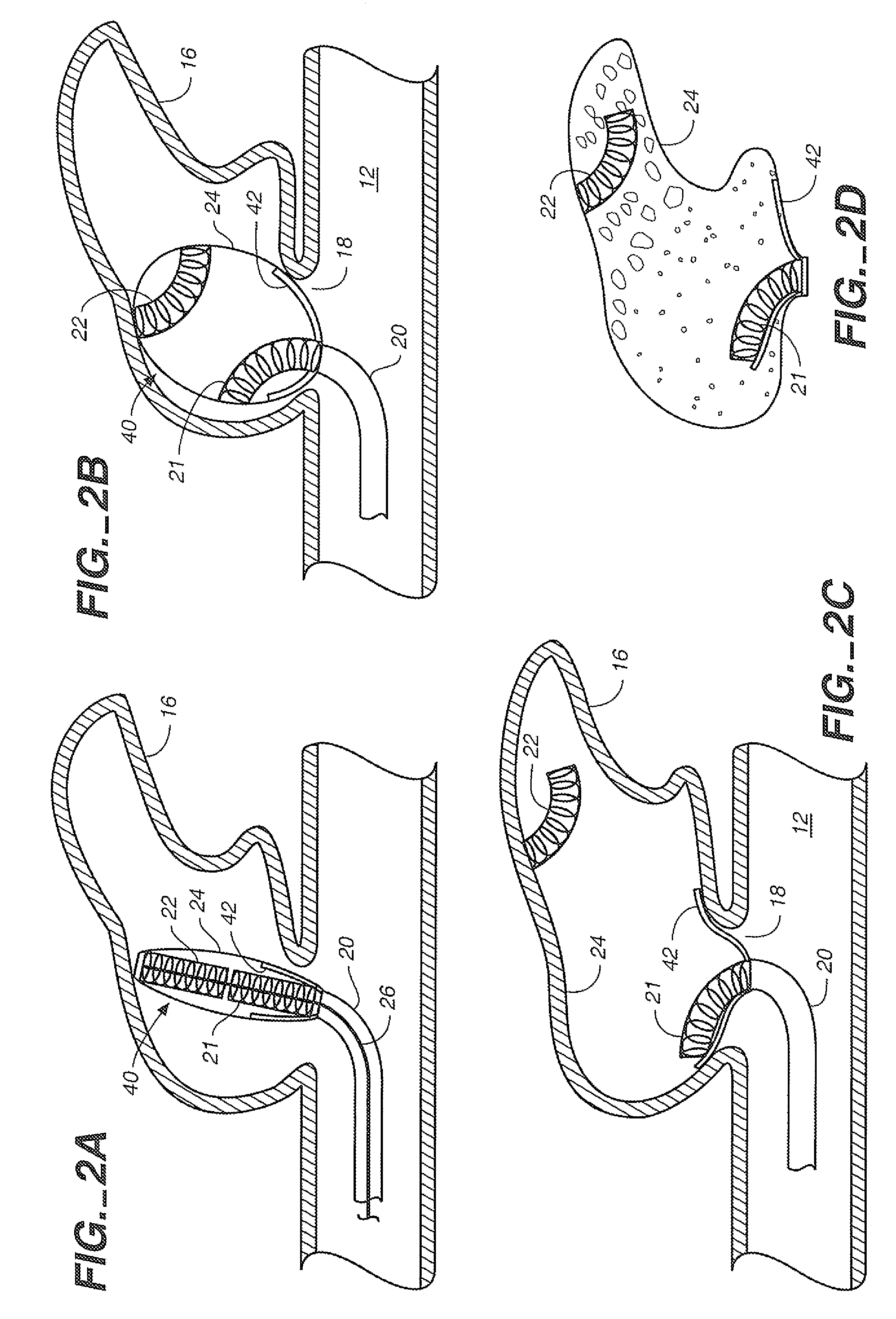
[0021]FIGS. 1A-1C illustrate a portion of an aneurysm treatment device 10 in a vessel 12 which has an aneurysm 14 therein, and thus illustrate the general context of the present invention. Though the embodiments discussed herein are discussed in conjunction with an aneurysm, it will be appreciated that they can be used in substantially any vascular cavity or other bodily cavities. Aneurysm 14 is defined by aneurysmal sac 16 and neck 18. Device 10 includes, in the embodiment illustrated, delivery catheter 18, a pair of extender coils 21 and 22 and an expandable liner 24 (aneurysm liner sac). Delivery catheter 20 has a proximal end that extends proximally to a position where it is manipulable by an operator. The distal end of catheter 20 is releaseably connected to the liner 24 and coil 21. Coils 21 and 22 can either be attached to the liner or catheter, or unattached. In addition, there can also be one or more coils disposed between coils 21 and 22 and axially aligned therewith.

[0022...


PUM


Abstract

The present invention is an aneurysm treatment device for treating aneurysms of various shapes and sizes.

Description

RELATED APPLICATION DATA[0001]This application is a continuation of co-pending U.S. patent application Ser. No. 10 / 107,689, filed Mar. 27, 2002, the priority of which is claimed under 35 U.S.C. §120, and the contents of which is incorporated herein by reference in its entirety, as though set forth in full.BACKGROUND OF THE INVENTION[0002]The present invention deals with a system for treating a vascular cavity. More specifically, the present invention is directed to vascular cavity liners and vascular cavity neck bridges.[0003]While the present discussion proceeds with respect to aneurysms, it will be appreciated that it can be applied to other vascular cavities (such as vessels, lumens, etc.) as well. An aneurysm or vascular malformation is a localized stretching or distension of an artery due to a weakening of the vessel wall. For example, “berry” aneurysms, i.e., small spherical distensions, occur in the vessels of the brain. The distension—often referred to as the aneurysm sac—is...

Claims


Application Information

Patent Timeline
Patent Type & Authority Applications(United States)
IPC IPC(8): A61M29/00A61B17/12A61M25/00
CPCA61B17/12022A61B17/12113A61B17/12136A61B17/12172A61B17/12177A61B2017/1205
Inventor BERENSTEIN, ALEJANDROEDER, JOSEPH C.
Owner STRYKER EURO OPERATIONS HLDG LLC
Why Eureka
Try Eureka