Reactor core and reactor

a reactor core and reactor technology, applied in the direction of transformer/inductance details, inductances, inductances with magnetic cores, etc., can solve the problems of large loss of high-frequency cores, limited core shape, and large loss of silicon steel sheets, and achieve the effect of increasing copper loss

Active Publication Date: 2010-07-08
HITACHI METALS LTD
View PDF1 Cites 44 Cited by
  • Summary
  • Abstract
  • Description
  • Claims
  • Application Information

AI Technical Summary

Benefits of technology

[0020]According to the present invention, it is possible to obtain a high-efficiency reactor core in wh

Problems solved by technology

However, silicon steel sheets have the disadvantage that high-frequency core losses are great, and amorphous soft magnetic sheet strips and nanocrystalline soft magnetic sheet strips have the disadvantage that the core shape is restricted by the wound core shape, the laminated core shape and the like, and cannot be easily shaped into such various shapes as those made of ferrite, which wil

Method used


Image

  • Reactor core and reactor
  • Reactor core and reactor
  • Reactor core and reactor

Examples


example 1

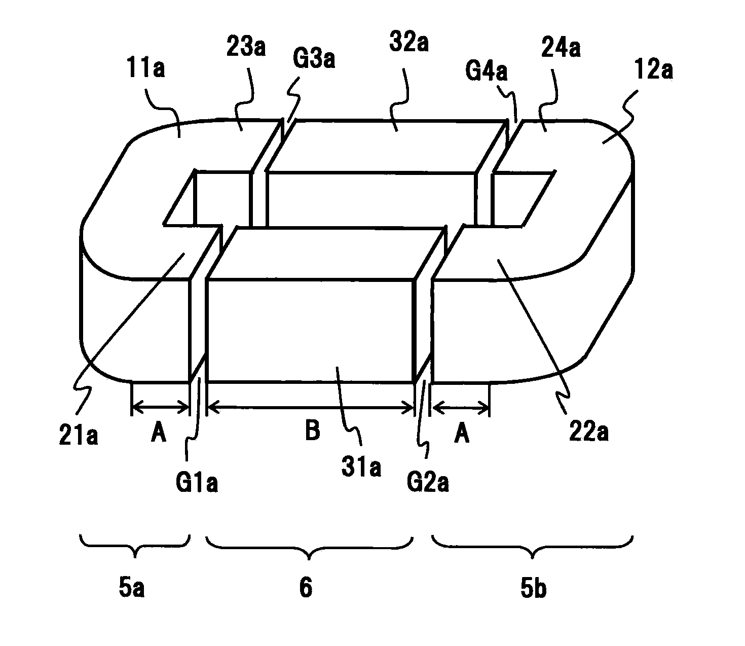
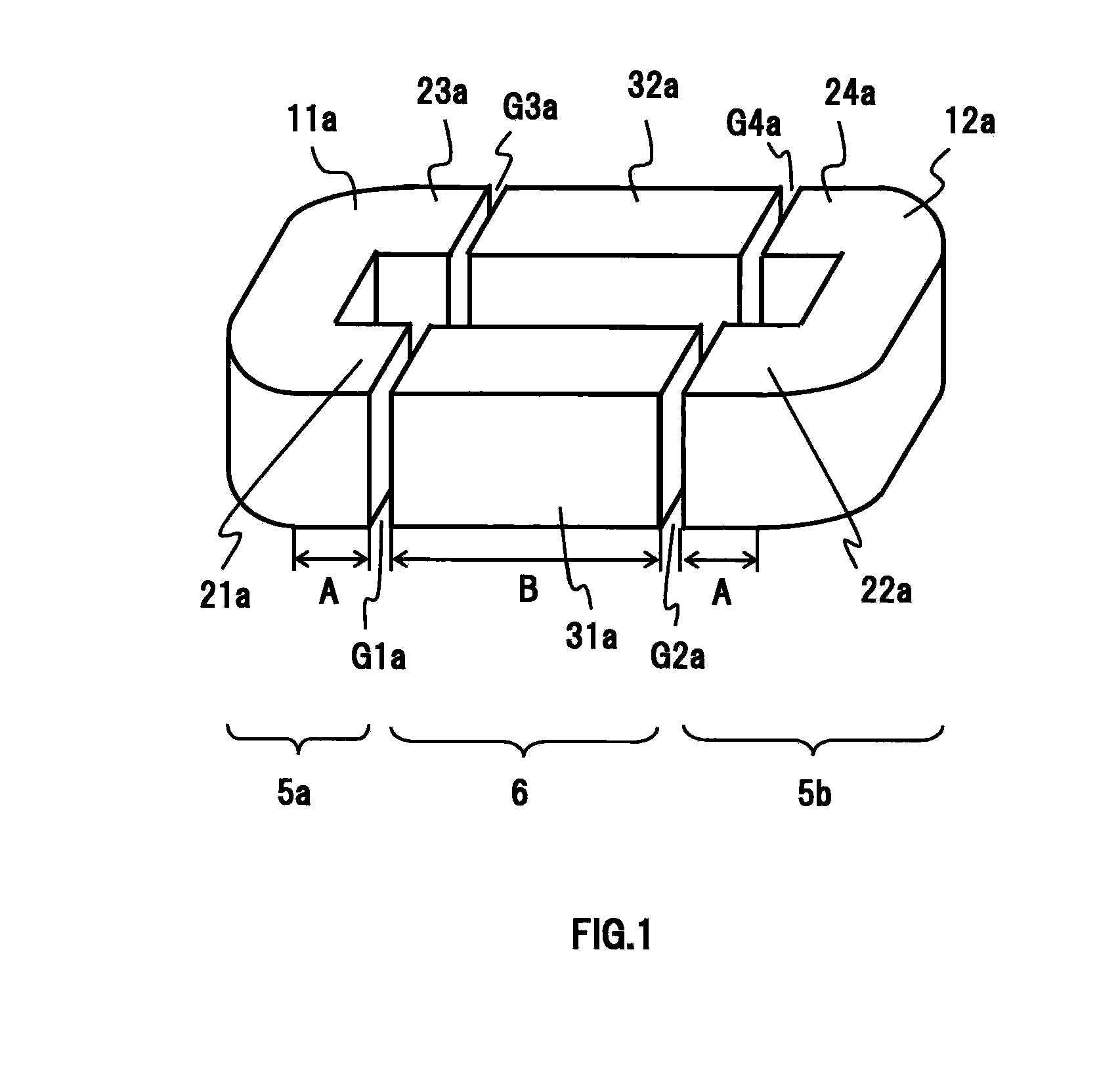
[0059]As a reactor core of the present invention, first, an annular reactor core having the shape shown in FIG. 1 was fabricated. In FIG. 1, the core joint 5a is a U-shaped core comprising the end portion 11a and the protrusions 21a, 23a, and the core joint 5b provided at the other end is a U-shaped core comprising the end portion 12a and the protrusions 22a, 24a. The end portion 11a and the protrusions 21a, 23a were fixed together, whereby the magnetically integrated core joint 5a was obtained. Similarly, the end portion 12a and the protrusions 22a, 24a were fixed together, whereby the magnetically integrated core joint 5b was obtained. Incidentally, the end portions (11a, 12a) and the protrusions (21a, 23a; 22a, 24a) may be formed as a one piece from the beginning in addition to the case where these are fixed together after being separately formed.

[0060]FIG. 3 is a diagram to explain the shape of the end portion 11a. In this figure, “h” denotes the height of the end portion 11a, “...

example 2

[0068]Annular reactor cores were fabricated in the same shape as in Example 1. The gap length (a length obtained by adding G1a to G4a) was doubled compared to the reactors of Example 1 and the adopted gap length was 10.8 mm (one side, 5.4 mm). The adopted width of each gap was constant. The adopted distance between the core joints 11a, 12a (a length obtained by adding the lengths of the protrusions 21a, 22a, the gaps G1a, G2a, and the I-shaped core block 31a) was 87.9 mm. The shape of the end portions 11a, 12a is the same as in Example 1. Also, with the shapes of the I-shaped core blocks 31a, 32a and the protrusions 21a, 22a being the same as in Example 1, annular reactor cores having the same shapes as shown in Table 1 were fabricated.

[0069]In the same manner as in Example 1, coils with 76 turns of the same wire material were mounted to the core legs of the reactor core and reactors with an inductance of approximately 275 μH at 60 A of a DC superimposed current were fabricated, and...

example 3

[0071]FIG. 6 is a diagram to explain an annular reactor core fabricated in this example. In FIG. 6, a core joint 5a is a U-shaped core comprising an end portion 11b and protrusions 21b, 23b, and a core joint 5b provided at the other end is a U-shaped core comprising an end portion 12b and protrusions 22b, 24b. The shape of the end portions 11b (and 12b) in this case is the same as already shown in FIG. 3.

[0072]Core legs 6, which are provided with I-shaped core blocks (31b, 33b) having a length B1 and I-shaped core blocks (32b, 34b) having a length B2, have a gap G formed between the core legs and the core joints 5a and 5b. The I-shaped core blocks 31b to 34b have the same sectional dimensions and the same shape as the protrusions 21b to 24b. The I-shaped core blocks 31b to 34b are disposed in a tandem manner each in a pair (31b and 32b; 34b and 35b), with gaps G1b, G2b and G3b formed between the I-shaped core blocks 31b, 32b and the protrusions 21b and 22b, and with gaps G4b, G5b an...


PUM


Abstract

Provided is an annular reactor core formed of a U-shaped core and core legs. Core joints including end portions and two protrusions form the U-shaped core. Between the protrusions of these core joints, a plurality of (two) core legs 6 formed of core blocks are arranged so as to have gaps and the protrusions. The ratio A/B, which is a ratio of the length A of the protrusions of the core joint to the average length B of the core blocks constituting the core legs in a magnetic path direction, is optimized so as to be not less than 0.3 but not more than 8.0, whereby an increase in copper loss due to leak magnetic fluxes of the gap portions is suppressed.

Description

TECHNICAL FIELD[0001]The present invention relates to a power circuit and, more particularly, to a reactor core and a reactor used in a hybrid electric vehicle.BACKGROUND ART[0002]Cores of power-circuit reactor can be broadly divided into three types. In the region of not more than several tens of kHz, silicon steel sheets, amorphous soft magnetic sheet strips, nanocrystalline soft magnetic sheet strips and the like are mainly used as core materials. These core materials contain iron as a main component and have the advantage that the saturation magnetic flux density Bs and magnetic permeability μ are great. However, silicon steel sheets have the disadvantage that high-frequency core losses are great, and amorphous soft magnetic sheet strips and nanocrystalline soft magnetic sheet strips have the disadvantage that the core shape is restricted by the wound core shape, the laminated core shape and the like, and cannot be easily shaped into such various shapes as those made of ferrite,...

Claims


Application Information

Patent Timeline
IPC IPC(8): H01F17/06
CPCH01F3/08H01F3/14H01F27/34H01F37/00
Inventor ABE, TORUHAMAKAKE, HIROKIKIKUCHI, KEIKO
Owner HITACHI METALS LTD
Why Eureka
Try Eureka