Video Decoder System for Movable Application

a decoder and video technology, applied in the field of video decoder systems, can solve the problems of large decoder systems, inability to receive tv signals correctly, and large electrical power consumption, and achieve the effect of reducing the memory area required

Active Publication Date: 2010-07-08
TEXAS INSTR INC
View PDF7 Cites 2 Cited by
  • Summary
  • Abstract
  • Description
  • Claims
  • Application Information

AI Technical Summary

Benefits of technology

[0010]This invention shares a single reference frame buffer between the HDTV tuner and the QVGA tuner. Thus this invention employs two tuners and a single MPEG decoder. The single MPEG decoder switches between the HDTV and the QVGA source bitstreams. The two bitstreams are based on same image data while differing in other ways such as image size. Because the two bitstreams include the same image data sharing reference frame buffers for the two bitstreams is possible. This invention reduce memory area required for the reference frames and displayed pictures and eliminates that need for one MPEG decoder.

Problems solved by technology

Providing two such tuner / MPEG decoder pairs consumes a disadvantageous amount of electric power and makes the decoder system large.
Sometimes the TV receiver can no longer receive the TV signal correctly.
For example, the receiver may not be able to receive the TV signal correctly near mountains or within tunnels.
Employing two such tuner / MPEG decoder pairs consumes a disadvantageous amount of electric power and makes the decoder system large.

Method used


Image

  • Video Decoder System for Movable Application
  • Video Decoder System for Movable Application
  • Video Decoder System for Movable Application

Examples


Embodiment Construction

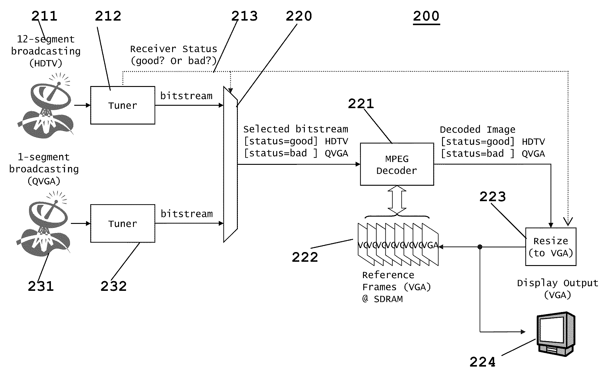
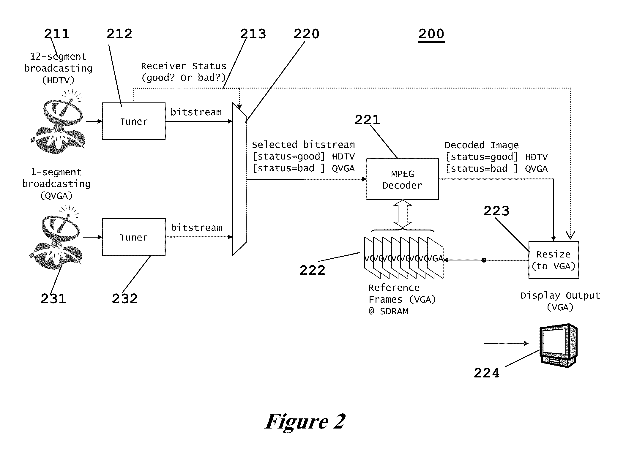
[0015]This invention is a DTV decoder system including two tuners, one for 12-segment HDTV broadcast and one is 1-segment QVGA broadcast, and a shared MPEG decoder.

[0016]FIG. 2 illustrates a block diagram of system 200 according to this invention. First antenna 21 receives the 12-segment HDTV broadcast and supplies the received signal to tuner 212. Tuner 112 detects the HDTV broadcast signal and supplies a bitstream to one input of multiplexer 220. Tuner 212 also produces a receiver status signal 213. Receiver status signal 213 is similar to receiver status signal 114 illustrated in FIG. 1. Receiver status signal 213 is a digital signal indicating the receiver status as good or bad.

[0017]Second antenna 231 receives the 1-segment QVGA broadcast and supplies the received signal to tuner 232. Tuner 132 detects the QVGA broadcast signal and supplies a bitstream to a second input of multiplexer 232.

[0018]MPEG decoder 133 employs a number of frame buffers 134. These are preferably stored ...


PUM


Abstract

This invention is a digital television receiver receiving alternative broadcasts. Separate tuners receive separate broadcast signals, such as 12-segment HDTV and 1-segment QVGA. A multiplexer selects one tuner based upon receiver status of a first tuner. The selected signal is decoded and resized for a display. The decoder uses a frame buffer of images in the resized size. In the preferred embodiment the input signals are a 12-segment HDTV broadcast and a 1-segment QVGA broadcast and the resized size is VGA.

Description

CLAIM OF PRIORITY[0001]This application claims priority under 35 U.S.C. 119(e)(1) to U.S. Provisional Application No. 61 / 114,236 filed Nov. 13, 2008.TECHNICAL FIELD OF THE INVENTION[0002]The technical field of this invention is a method for video decoder system with plural tuners used in movable applications such as a car navigation system or mobile PC or phone.BACKGROUND OF THE INVENTION[0003]The decoder system of digital TV broadcast receiver used on a movable platform, such as a car navigation system, requires a tuner and Motion Picture Expert's Group (MPEG) decoder pair for each bitstream of HDTV (12-segment) and QVGA (1-segment), independently. This requirement remains even though only one of inputs is selected as source of displayed images. Providing two such tuner / MPEG decoder pairs consumes a disadvantageous amount of electric power and makes the decoder system large.[0004]It is feasible in the current art to watch digital TV broadcast programs on movable platforms such as c...

Claims


Application Information

Patent Timeline
Patent Type & Authority Applications(United States)
IPC IPC(8): H04N5/50
CPCH04H20/57H04H2201/60H04N5/4401H04N5/46H04N5/50H04N21/41407H04N21/4263H04N21/440263H04N21/44209H04N21/4621H04N21/4622H04N21/426
Inventor MINAGAWA, YUSUKEYAMAUCHI, SATORU
Owner TEXAS INSTR INC
Why Eureka
Try Eureka