Image decoding device and image decoding method

a decoding device and image technology, applied in the field of image decoding devices and methods, can solve the problems of increasing the memory carried, increasing the consumption power of the image processor, increasing the size of the chip, and reducing the duration of continuous use of the equipment. , to achieve the effect of reducing the memory area

Inactive Publication Date: 2005-07-19
PANASONIC CORP
View PDF10 Cites 2 Cited by
  • Summary
  • Abstract
  • Description
  • Claims
  • Application Information

AI Technical Summary

Benefits of technology

[0022]Performing the prediction process by repeating such a copying process eliminates the need to hold the DC components and AC components of the block, located immediately prior and adjacently to the left side of the current target macro block, for the prediction process of the current target macro block in the predicted value storage means.
[0023]As a result of the above, it is sufficient to secure just an area for holding at least the DC components and AC components of one target macro block in the predicted luminance value storage means.
[0024]The memory area used for the prediction process in the decoding of coded image signals is thus further reduced.

Problems solved by technology

In actuality, an image processor that realizes a prediction process is limited by its storage capacity and cannot carry an unlimited amount of memory.
Increasing the memory carried increases the consumption power of the image processor and increases of the chip size.
This decreases the duration of continuous use of the equipment loaded with the processor and increases the production cost of the processor.

Method used


Image

  • Image decoding device and image decoding method
  • Image decoding device and image decoding method
  • Image decoding device and image decoding method

Examples


embodiment 1

(Embodiment 1)

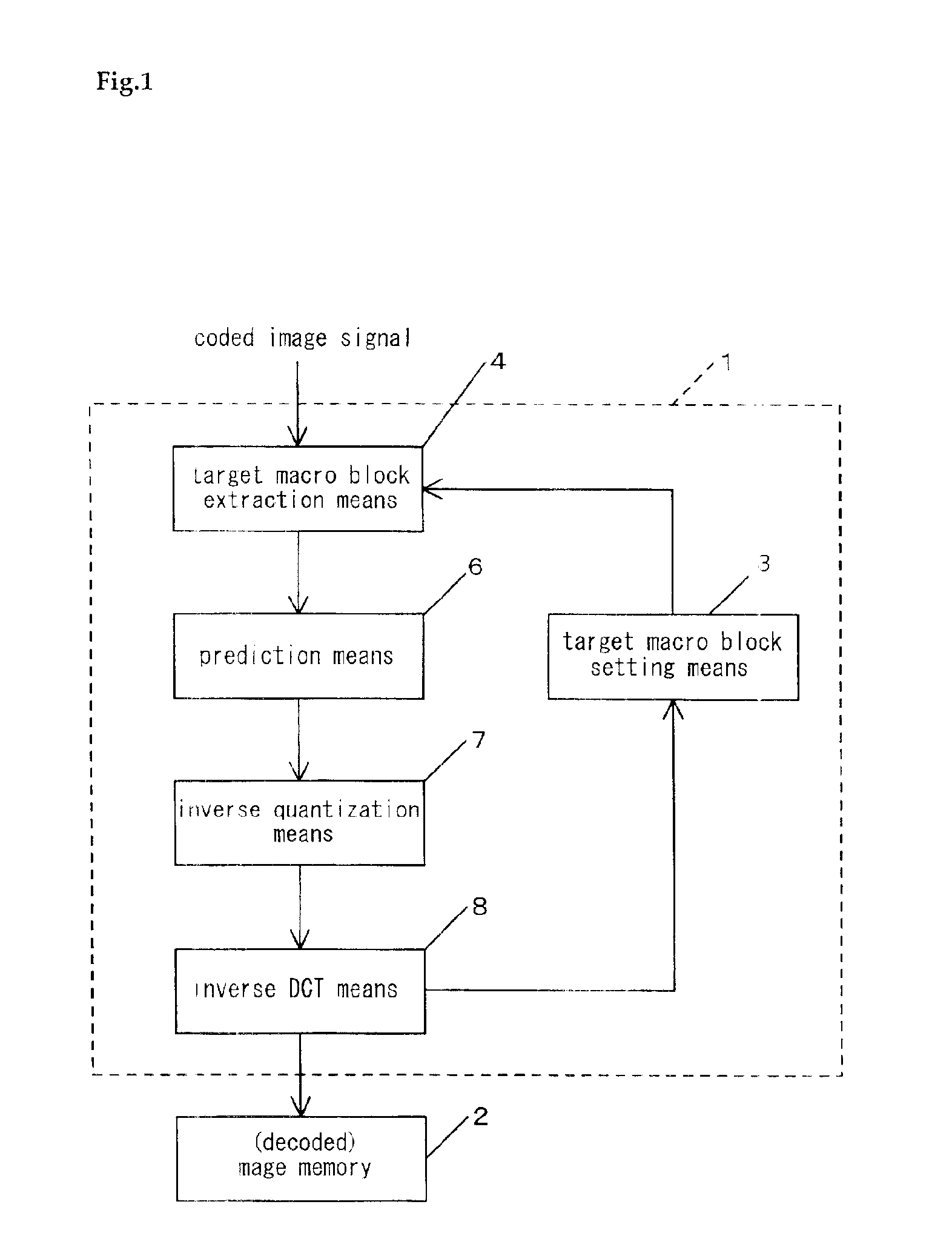
[0049]Referring to FIG. 1, an image decoding device of an embodiment of the invention, shown generally at 1, decodes and outputs the resulting data to an image memory 2. The data entering the image memory 2 is in target macro block units that are coded image signals coded by DCT (discrete cosine transform), quantization, and variable-length coding.

[0050]Image decoding device 1 is equipped with a target macro block setting means 3, a target macro block extraction means 4, a prediction means 6, an inverse quantization means 7, and an inverse DCT means 8.

[0051]Target macro block setting means 3 selects the target macro block to be decoded from among the entire image size, for example, by designating position information or a block number, etc. Target macro block extraction means 4 performs a variable length decoding process and a zigzag scan on the coded image signal and extracts the data of the selected target macro block.

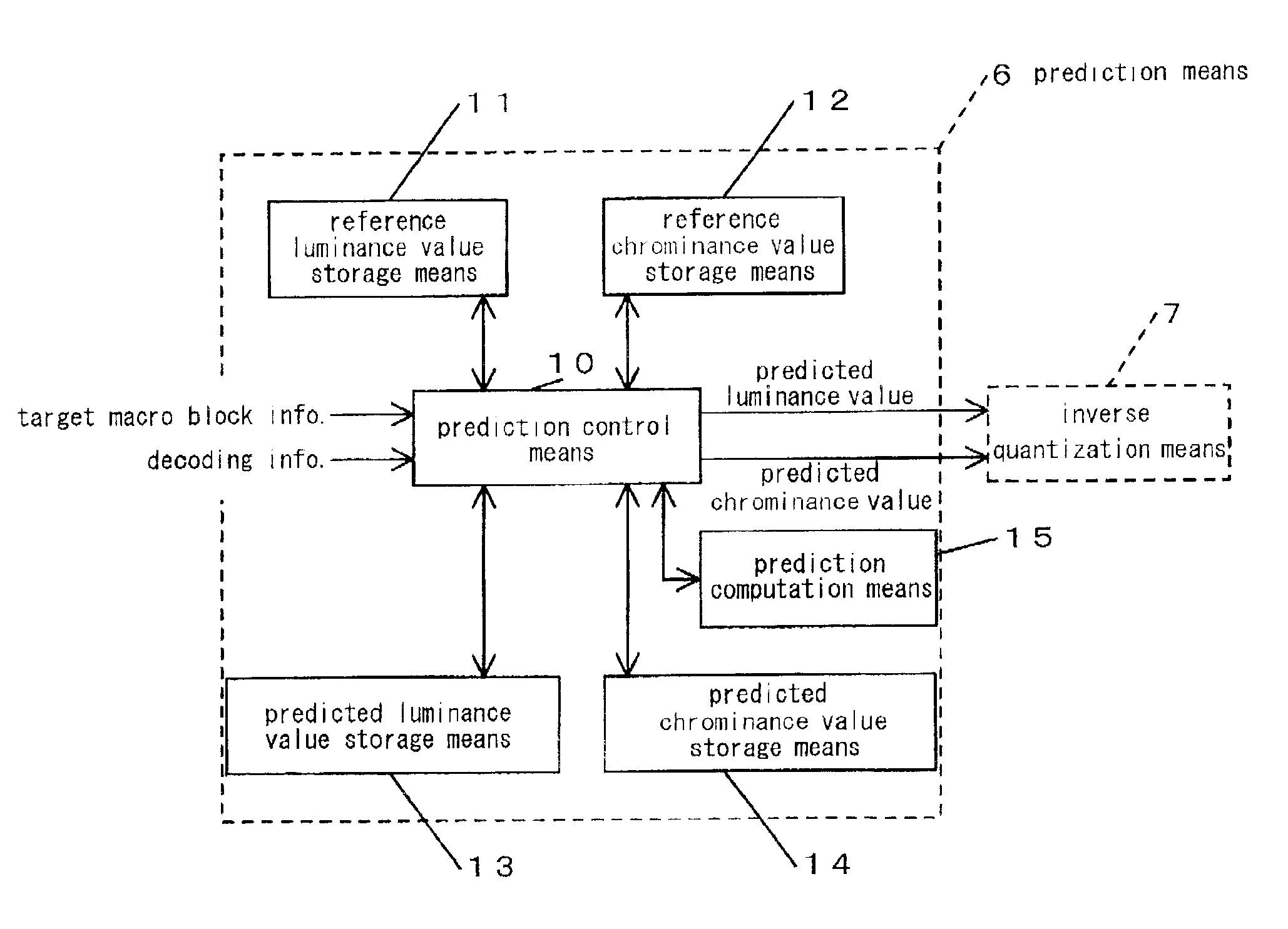
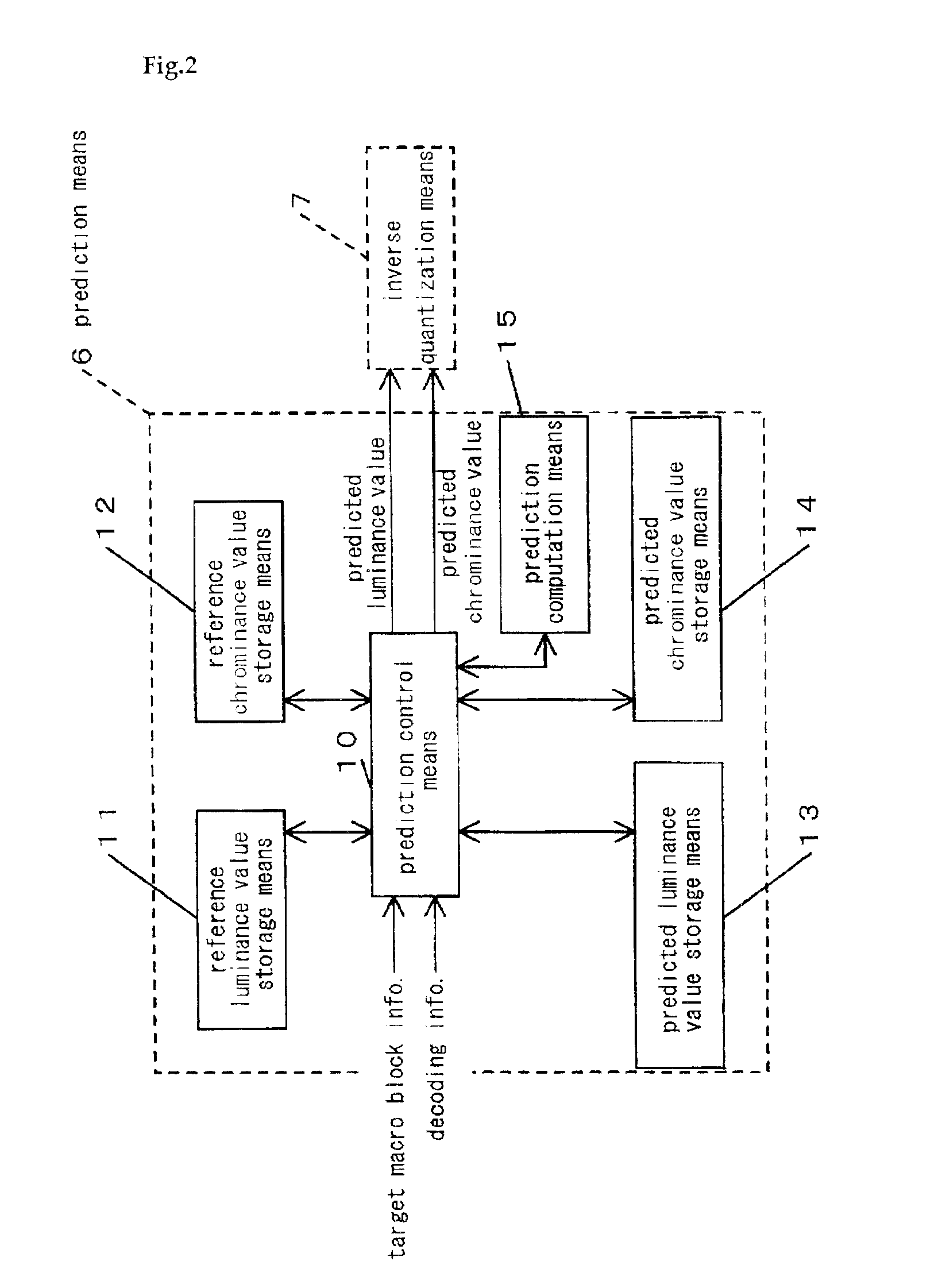
[0052]Prediction means 6 performs a DC / AC predict...

embodiment 2

(Embodiment 2)

[0142]The overall arrangement of the image decoding device of Embodiment 2 of this invention is the same as that of the image decoding device of FIG. 1, and the prediction means of the image decoding device of Embodiment 2 is the same as that of the prediction means shown in FIG. 2.

[0143]Also, the principles of DC / AC prediction (principles of prediction computation) carried out by the prediction means of Embodiment 2 are the same as the prediction computation principles that were described using FIGS. 3 through 5. The overall flow of the processes carried out by the image decoding device of Embodiment 2 are also the same as the flow shown in FIG. 6.

[0144]The image decoding device of Embodiment 2 differs from the image decoding device of Embodiment 1 in the method of the prediction process carried out by prediction means 6. A description that mainly concerns this aspect is now given with reference to FIGS. 13 through 19.

[0145]First, the details of reference luminance va...


PUM


Abstract

After completion of a prediction process for a single line in an image of size S, the DC components and AC components, held in a lower stage part of a predicted luminance value storage are copied into a line part. This copying is done to use the DC components and AC components that have been copied into line part as reference values for the prediction process of the target macro blocks of the next single line. Performing the prediction process while repeating such copying eliminates the need to secure the area for storing of the DC components and AC components of the entire image size in predicted luminance value storage for the prediction process.

Description

BACKGROUND OF THE INVENTION[0001]1. Field of the Invention[0002]This invention concerns an image decoding device and method for decoding, in target macro block units, coded image signals that are coded by DCT, quantization, and variable-length coding.[0003]2. Description of the Related Art[0004]In the field of image coding technology, a standard called MPEG4 is specified and standardized in the specifications titled, “ISO / IEC14496-2 Information Technology—Generic Coding of Audio-Visual Object.”[0005]However, this document does not describe methods of implementing the decoding of image signals coded in accordance with MPEG4.[0006]Also, though the book titled “MPEG-4 No Subete” (Japanese term meaning “All About MPEG4”; Miki et al, 1998, published by Kogyo Chosakai Publishing Co., Ltd.) provides a description of the principles of a decoding method for this type of coded signal, it does not provide specific methods of implementation. Besides the above, substantial literature concerning ...

Claims


Application Information

Patent Timeline
Patent Type & Authority Patents(United States)
IPC IPC(8): H04N7/34H04N7/30H04N11/04H03M7/30H04N19/423H04N19/426H04N19/44H04N19/50H04N19/625H04N19/91
CPCH04N19/593H04N19/63H04N19/61
Inventor KAJITA, SATOSHIYOKOYAMA, SHINTARO
Owner PANASONIC CORP
Why Eureka
Try Eureka