Optimal dimensional and mechanical properties of laser sintered hardware by thermal analysis and parameter optimization

a laser sintering and thermal analysis technology, applied in the direction of additive manufacturing processes, manufacturing tools, instruments, etc., can solve the problems of reducing the time required to produce a rapid prototype, affecting the quality of laser sintering parts, etc., to achieve the effect of reducing deviation

Inactive Publication Date: 2010-07-08
ROCKETDYNE
View PDF52 Cites 81 Cited by
  • Summary
  • Abstract
  • Description
  • Claims
  • Application Information

AI Technical Summary

Problems solved by technology

Thus, the time required to produce a rapid prototype is significantly shorter than with conventional methods such as sheet metal forming, machining, molding, or other methods known in the art.
Further, powder materials that are presently used for selective laser sintering generally have relatively low mechanical properties due to the nature of the rapid prototype application.
Accordingly, parts formed using selective laser sintering are typically not used within a production design or as production parts due to limited performance capabilities such as low or inconsistent mechanical properties.
Aerospace parts have relatively stringent design requirements compared with parts in other applications, primarily due to operating environments having extremely high loads and temperatures in addition to a relatively high amount of parts in a relatively small volume.
The inventory required, however, is extremely expensive and storing, cataloging and quickly retrieving parts presents myriad difficulties and significant cost.
On the other hand, having only exactly what parts are needed at the point at which the demand exists may be ideal, but implementation difficulties and large scale integration concerns make this generally impossible.

Method used


Image

  • Optimal dimensional and mechanical properties of laser sintered hardware by thermal analysis and parameter optimization
  • Optimal dimensional and mechanical properties of laser sintered hardware by thermal analysis and parameter optimization
  • Optimal dimensional and mechanical properties of laser sintered hardware by thermal analysis and parameter optimization

Examples


Embodiment Construction

[0019]The following description of the preferred implementations is merely exemplary in nature and is in no way intended to limit the invention, its application, or uses. Additionally, the selective laser sintering process as well as other rapid prototyping processes are well known by those skilled in the art and will therefore not be described herein in extensive detail.

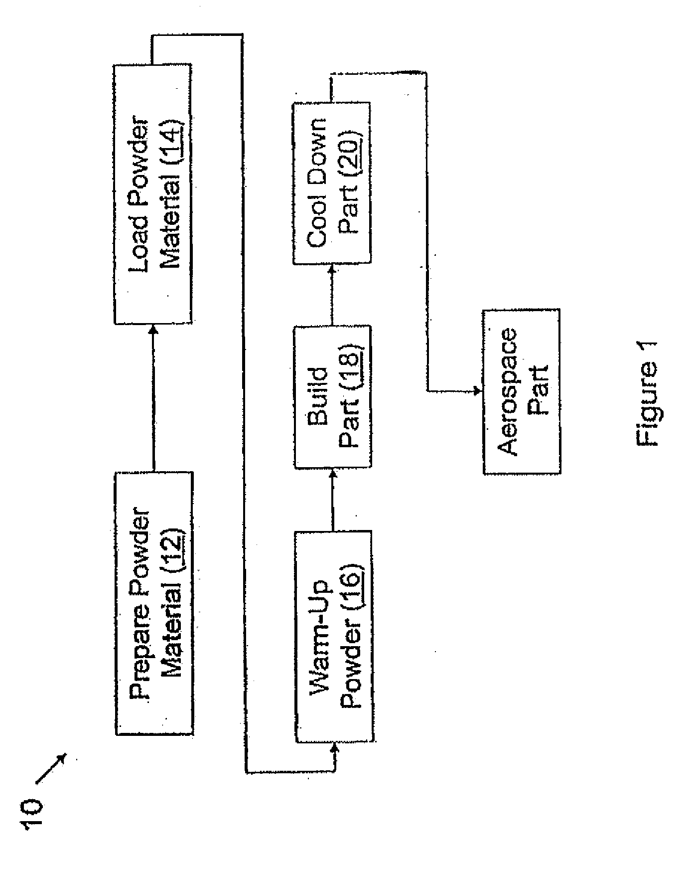
[0020]Referring to FIG. 1, a process of fabricating at least one aerospace part according to the present invention is represented in a flow diagram format as indicated by reference numeral 10. As shown, the process generally comprises a step 12 of preparing a powder material, loading the powder material, per step 14, into a laser sintering machine, warming up the powder material at step 16, building the part at step 18, and cooling down the part at step 20. Additionally, the process 10 includes several build and part parameters, which are characterized as either “hidden,”“fixed,” or “variable.” The hidden and fixed ...


PUM

PropertyMeasurementUnit
temperatureaaaaaaaaaa

Abstract

A process for establishing manufacturing parameters includes computer simulating a manufacture of a laser-sintered part based on a set of manufacturing parameters, calculating a set of physical properties of the simulated manufacture, and modifying the set of manufacturing parameters based on the calculated set in order to obtain a desired set of physical properties.

Description

CROSS-REFERENCE TO RELATED APPLICATIONS[0001]This application is a continuation-in-part of U.S. patent application Ser. No. 10 / 458,636, filed on Jun. 10, 2003, and related U.S. application Ser. No. 10 / 205,451, filed on Jul. 25, 2002, which is abandoned.FIELD OF THE INVENTION[0002]The present invention relates generally to rapid prototype machines and more particularly to optimization of build runs using a selective laser sintering machine or the like.BACKGROUND OF THE INVENTION[0003]Methods of rapid prototyping, such as selective laser sintering (SLS), are well known in the art and have traditionally been employed to produce parts known as “rapid prototypes,” which are parts that are used to demonstrate a proof of concept or a requirement such as proper form and fit. The selective laser sintering process generally consists of producing parts in layers from a laser-fusible powder that is provided one layer at a time. The powder is fused, or sintered, by the application of laser energ...

Claims


Application Information

Patent Timeline
Patent Type & Authority Applications(United States)
IPC IPC(8): G06G7/66B29C35/08G06F17/50
CPCB22F2998/00B29C67/0051B29C67/0077B29C67/0088B22F2003/1057B29C2037/90B22F3/1055B22F2203/03B33Y10/00B33Y50/02B29C64/153B29C64/371B29C64/393Y02P10/25B22F10/80B22F10/36B22F10/28
Inventor FINK, JEFFREY E.TAYLOR, TRACY L.NARVETT, LORI A.SHAPEY, BRYON L.
Owner ROCKETDYNE
Why Eureka
Try Eureka