
Elastic clip

a technology of elastic clips and clips, applied in the field of elastic clips, can solve the problems of high cost, difficult mass production, and a lot of effort and time for structure assembly, and achieve the effect of reducing labor costs and facilitating fabrication and assembly

Inactive Publication Date: 2010-07-15
CHANG PI CHENG
View PDF9 Cites 6 Cited by
  • Summary
  • Abstract
  • Description
  • Claims
  • Application Information

AI Technical Summary

Benefits of technology

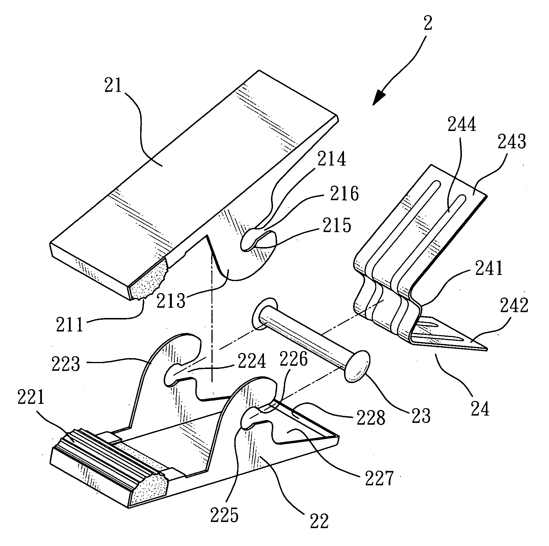
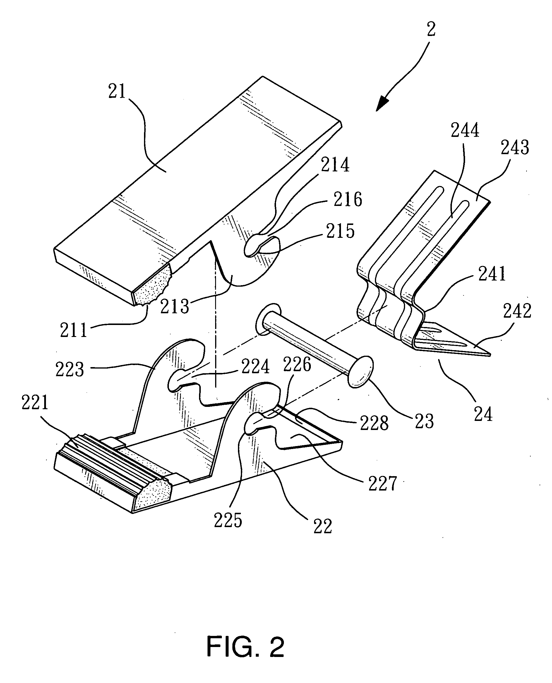
[0005]In view of the aforesaid problems, the primary object of the present invention is to provide an elastic clip that can be fabricated and assembled easily. It includes a first clipping blade, a second clipping blade, a pin and an elastic reed. The first clipping blade and the second clipping blade face each other, and have respectively a pair of lugs in the middle corresponding to each other. Each lug has a transverse notch and a pin hole at a tail end of the notch to be wedged in transversely by the pin to couple the first and second clipping blades. The pin serves as a movement axis. The elastic reed is positioned between the first and second clipping blades by pushing from a rear side. The elastic reed has a first side blade and a second side blade retained by the first and second clipping blades, and a curved portion in the middle to press and surround the pin. Such a structure allows assembly to be done quickly and labor cost can be reduced. It provides significant benefits over the conventional technique.
[0006]The side blades of the elastic reed also have at least one reinforced rib to increase the elastic strength thereof.

Problems solved by technology

Such a structure requires a lot of efforts and time to do assembly.
Mass production is difficult and the cost is higher.
Product competitiveness suffers.

Method used


Image

  • Elastic clip
  • Elastic clip
  • Elastic clip

Examples


Embodiment Construction

[0013]Referring to FIGS. 2 and 3, the invention provides an elastic clip 2 which includes a first clipping blade 21, a second clipping blade 22, a pin 23 and an elastic reed 24. The first clipping blade 21 and the second clipping blade 22 face each other.

[0014]The first clipping blade 21 has a first clipping portion 211 at a front end, a first depressing portion 212 at a rear end and a first inner recess 217 on an inner side that has a rear end formed a first detent wall 218. It also has a pair of first lugs 213 in a middle portion corresponding to each other. Each first lug 213 has a first transverse notch 214 and a first pin hole 215 at a tail end of the first transverse notch 214. The first pin hole 215 and the first transverse notch 214 are joined at a slightly protrusive juncture to form a first retaining spot 216.

[0015]The second clipping blade 22 has a second clipping portion 221 at a front end, a second depressing portion 222 at a rear end and a second inner recess 227 on an...


PUM


Abstract

An elastic clip that can be fabricated and assembled easily includes a first clipping blade, a second clipping blade, a pin and an elastic reed. The first clipping blade and second clipping blade face each other, and have respectively a pair of lugs in the middle corresponding to each other. Each lug has a transverse notch and a pin hole at a tail end of the notch to be wedged in transversely by the pin to couple the first and second clipping blades. The pin serves as a movement axis. The elastic reed is disposed between the first and second clipping blades by pushing from a rear side. The elastic reed has a first side blade and a second side blade retained by the first and second clipping blades, and a curved portion in the middle to press and surround the pin. Thus assembly can be done quickly and labor cost can be reduced. It provides significant improvements over the conventional elastic clip.

Description

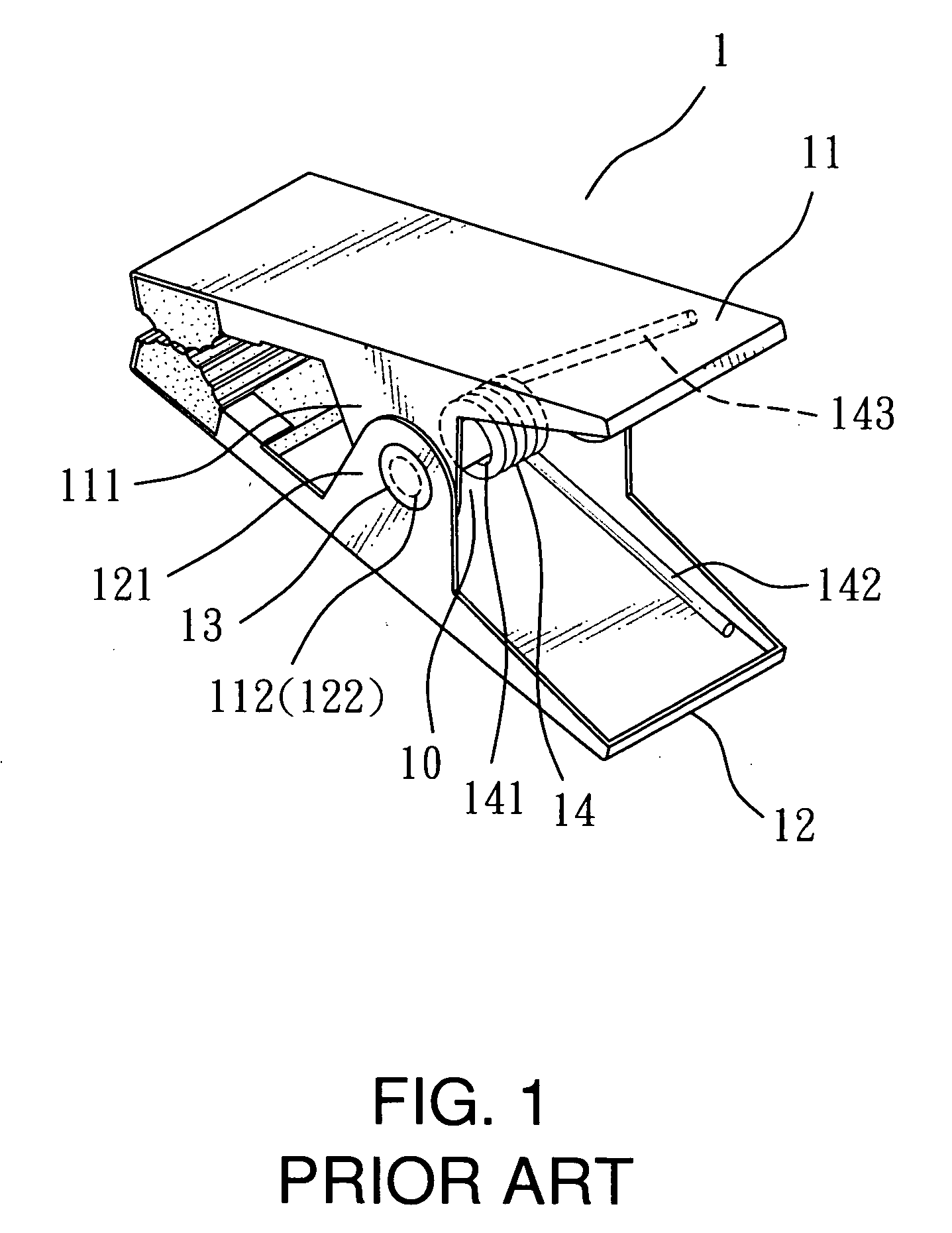
BACKGROUND OF THE INVENTION[0001]1. Field of the Invention[0002]The present invention relates to an elastic clip that is easily fabricated and assembled at a lower labor cost.[0003]2. Description of the Prior Art[0004]A conventional elastic clip 1, referring to FIG. 1, is widely used. For instances clothespins, stationery clips, hairclips and the like mostly adopt such a structure. The elastic clip 1 mainly includes a first clipping blade 11, a second clipping blade 12, a pin 13 and a torsional spring 14. The first and second clipping blades 11 and 12 face each other and have respectively a pair of lugs 111 and 121 in the center corresponding to each other. The lugs 111 and 121 have respectively a pin hole 112 and 122, and are spaced from each other to form a space 10 between them to hold the torsional spring 14. For assembly, first, dispose the torsional spring 14 in the space 10; position the first and second clipping blades 11 and 12 to face each other; insert the pin 13 into the...

Claims


Application Information

Patent Timeline
Patent Type & Authority Applications(United States)
IPC IPC(8): A44B21/00
CPCA45D8/20A45F5/02Y10T24/44641D06F55/02A45F2200/055
Inventor CHANG, MEI HUI
Owner CHANG PI CHENG
Learn More