
Haymaking implement for displacing crop lying on the ground

a technology for displacing crop and implement, which is applied in the field of haymaking implements, can solve the problems of insufficient accuracy of swath formation and lack of swath formation, and achieve the effects of less contamination, inexpensive and simple production

Inactive Publication Date: 2010-07-15
LELY PATENT
View PDF5 Cites 2 Cited by
  • Summary
  • Abstract
  • Description
  • Claims
  • Application Information

AI Technical Summary

Benefits of technology

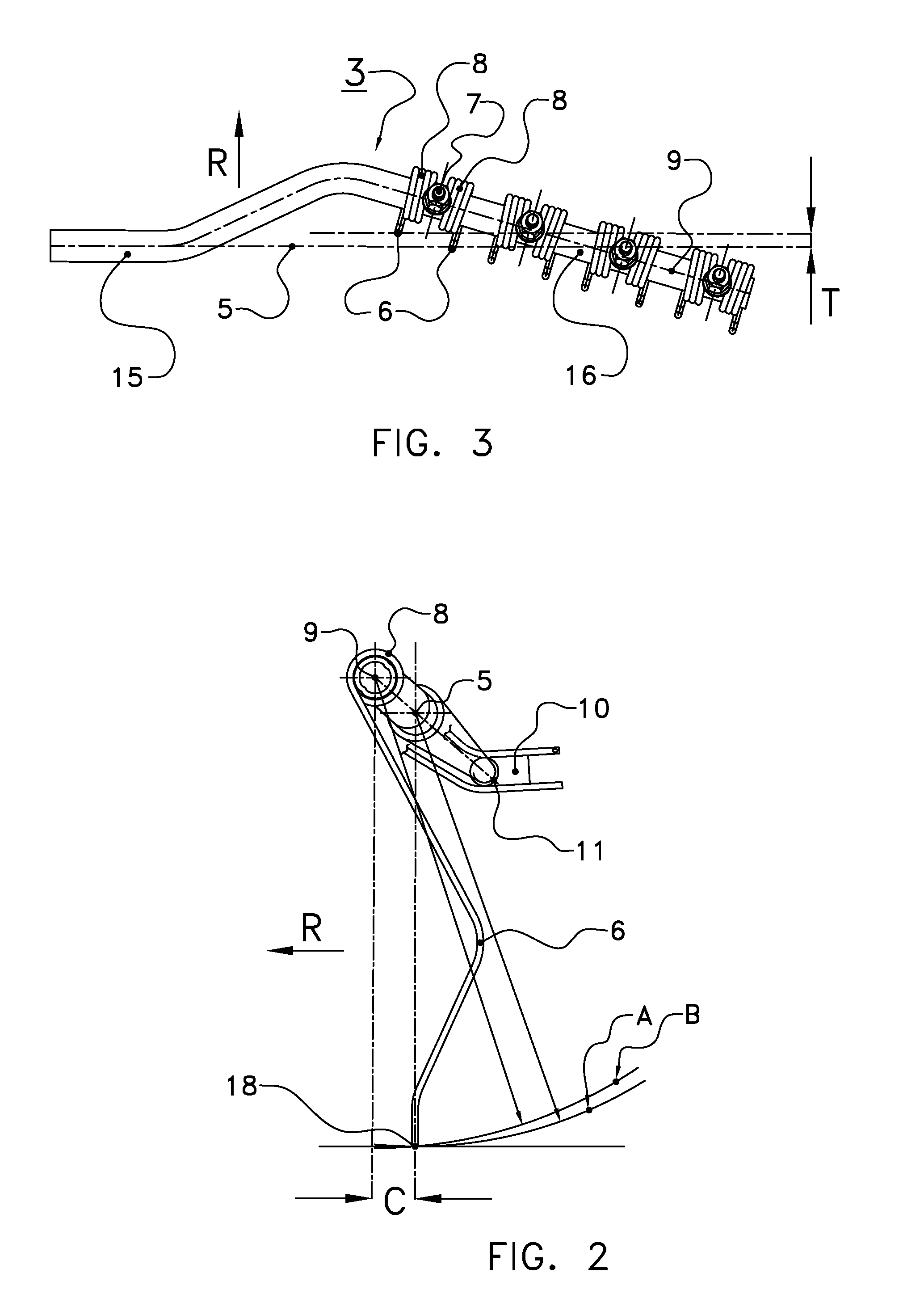
[0012]In particular, in the gripping position, for at least one of the tine points, and preferably for all the tine points, the incremental upward displacement in the case of rotation about the spring axis is greater than zero. If the tine hits an obstacle, such as a stone, the arm will deflect under spring pressure and rotate about the centre of the winding. This is called obstacle protection. Right at the first contact with an obstacle, such as a stone, the tine will react by rotation about the axis of symmetry of the spring and will perform, according to the invention, as a result thereof an initial motion having a vertical upward component. As a result thereof, the tine will move upward quickly and it will easily be possible to avoid the obstacle.
[0013]In a preferred embodiment, in the gripping position, for at least one of the tine points, and preferably for all the tine points, the incremental upward displacement in the case of rotation about the spring axis is greater than in the case of rotation about the pivot axis. The obstacle protection is thus even more efficient than the pivoting motion about the pivot axis which will occur in any case, but later. The transition from the gripping position to the release position takes place by means of a rotation about the pivot axis. At the beginning of the pivoting motion, the motion of the tine point will have no vertical component or a much smaller vertical component. As a result thereof, at the transition to the release position, the tine point will maintain for a relatively long time substantially the same position as in the complete gripping position, and will subsequently pass very quickly to the release position. In fact, the obstacle protection and the rapid transition from the gripping position to the release position are thus effectively separated.
[0014]Viewed in the direction of rotation, the centre of the spring portion of at least one of the tines is advantageously located in front of the pivot axis. This is a simple manner of ensuring that the incremental displacement of the tine point is orientated upwardly when an obstacle is met.
[0016]Advantageously, the distance between the tine point and the spring axis is smaller than the distance between the tine point and the pivot axis at the position of the tine point. In this, alternative, embodiment, there is, on the contrary, provided a relatively short tine which, however, in particular if the centre of the spring portion is positioned in front of the pivot axis, has an excellent obstacle protection.
[0018]In particular, the spring portion is connected to the pivot arm by means of a connecting piece, and the spring axis and the outer arm portion are located at a mutual distance of, preferably, at least the diameter of the spring portion. Thus, in this case, the spring portion does not surround the pivot arm. This provides even more possibilities of disconnecting the obstacle protection from the actual pivoting motion. Alternatively, the spring portion may surround the pivot arm, in which case the advantage of lesser contamination is provided. Moreover, in the case of breakage in the spring portion, the remaining parts will not come loose from the tine arm.
[0019]Furthermore, it is advantageous if the outer arm portion and the inner arm portion form an integral whole. This enables an inexpensive and simple production of the tine arm, starting from a tube.

Problems solved by technology

Despite the above-mentioned improvements, in practice, the swath formation is still sometimes found to be lacking.
In particular, swath formation may be insufficiently accurate.

Method used


Image

  • Haymaking implement for displacing crop lying on the ground
  • Haymaking implement for displacing crop lying on the ground
  • Haymaking implement for displacing crop lying on the ground

Examples


Embodiment Construction

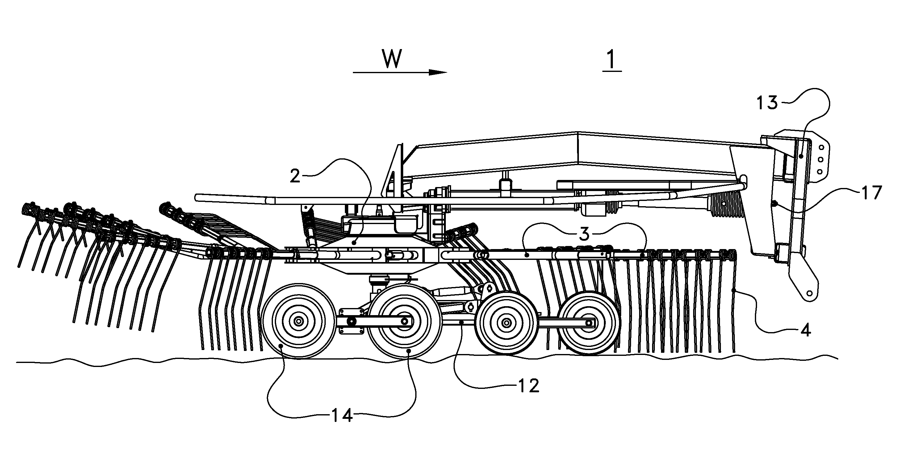
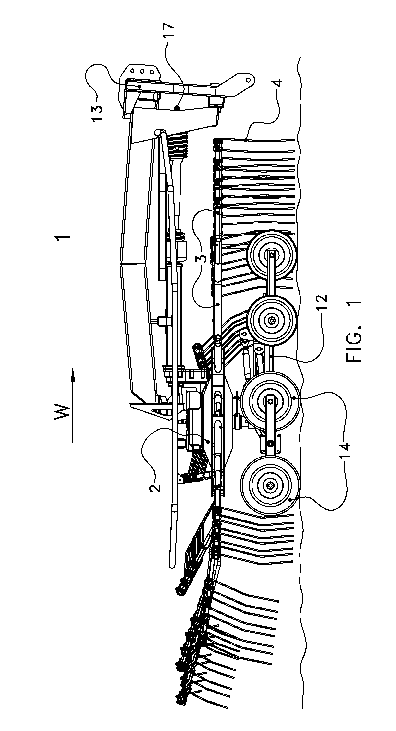
[0025]The following is a description of certain embodiments of the invention, given by way of example only and with reference to the drawings. Referring to FIG. 1, a haymaking implement 1 for displacing crop lying on the ground is shown, comprising at least one rotor 2 which is rotatable about an upwardly orientated axis and which is provided with at least one tine arm 3, wherein the tine arm 3 is pivotably fastened to the rotor 2 about an associated pivot axis 5, wherein the tine arm 3 comprises an inner arm portion 15 and an outer arm portion 16 having a plurality of tines 4, wherein the tine arm 3 is mechanically controllable in such a manner that the position of the tines 4 during operation varies cyclically between a gripping position for gripping and taking along crop lying on the ground and a release position for releasing the crop, wherein each tine 4 comprises a tine portion 6 having a tine point 18 for contact with the crop, a fastening portion 7 for fastening on the tine ...


PUM


Abstract

A haymaking implement for displacing crop lying on the ground has a rotor and at least one tine arm, wherein the tine arm is pivotable with respect to the rotor about an associated pivot axis, for movement between a gripping position for gripping and taking along crop lying on the ground and a release position for releasing the crop. The tine arm has an outer arm portion carrying a plurality of tines, wherein each tine comprises a tine point for contact with the crop. In the gripping position, an innermost tine point positioned relatively closest to the rotor axis is located on or in front of the pivot axis with respect to the direction of rotation (R), while an outermost tine point positioned relatively distant from the rotor axis is located behind the pivot axis.

Description

CROSS REFERENCE TO RELATED APPLICATIONS[0001]This application claims priority from Dutch application No. 1034442 filed on 28 Sep. 2007 and is a continuation in part of PCT International Application No. PCT / NL2008 / 000152 filed on 19 Jun. 2008, the contents of both of which are hereby incorporated by reference in their entirety.BACKGROUND OF THE INVENTION[0002]1. Field of the Invention[0003]The invention relates generally to haymaking implements for displacing crop lying on the ground and more particularly to a haymaking implement comprising a rotor having arms which are rotatable about an associated pivot axis.[0004]2. Description of the Related Art[0005]Haymaking implements are known comprising rotors that are rotatable about generally upstanding axes. The rotors are provided with arms which are themselves rotatable about an associated pivot axis. Tines are fastened on the ends of these arms. The outer end of an arm may be obliquely disposed relative to an inner portion. Owing to th...

Claims


Application Information

Patent Timeline
Patent Type & Authority Applications(United States)
IPC IPC(8): A01D80/02A01D78/08
CPCA01D78/125
Inventor VAN DEN ENGEL, ALFONSUS JACOBUSVAN DER LELIJ, BART
Owner LELY PATENT
Learn More