Acoustic sensor

Active Publication Date: 2010-07-15
MMI SEMICON CO LTD
View PDF2 Cites 26 Cited by
  • Summary
  • Abstract
  • Description
  • Claims
  • Application Information

AI Technical Summary

Benefits of technology

[0036]In the acoustic sensor (of the second different aspect) in which the outer circumferential portion of the movable portion of the vibrating electrode plate is partially fixed to the substrate at plural points, the local sticking is easily generated in the region located in the middle of the fixed sites on the vibrating electrode plate or the sites facing the fixed sites on the vibrating electrode plate. Therefore, the local sticking can be reduced by relatively decreasing the interval between the adjacent projections in this region. The whole sticking of the vibrating electrode plate can be reduced by increasing the interval between the adjacent projections in other projection forming regions where the local sticking is hardly generated.
[0037]In the acoustic sensor according to another different aspect of the present invention, the projections are arranged along a plurality of concentric circles or a plurality of polygons. Because the deflections of the vibrating electrode plate are often distributed in the concentric circular shapes or the concentric polygonal shapes, the sticking of the vibrating electrode plate can evenly and efficiently be avoided by arranging the projections along the concentric circles or polygons.
[0038]In the acoustic sensor according to still another different aspect of the present invention, the counter electrode plate includes a plurality of acoustic perforations in order to pass the sound pressure, and each of the projections is disposed in a central portion of a region surrounded by the acoustic perforations. This aspect facilitates production of the acoustic perforations and the projections because the acoustic perforations and the projections can be provided distant from each other as much as possible.
[003

Problems solved by technology

However, when the elastic restoring force Q of the vibrating electrode plate 12 is increased, the vibrating electrode p

Method used


Image

  • Acoustic sensor
  • Acoustic sensor
  • Acoustic sensor

Examples


Example

First Embodiment

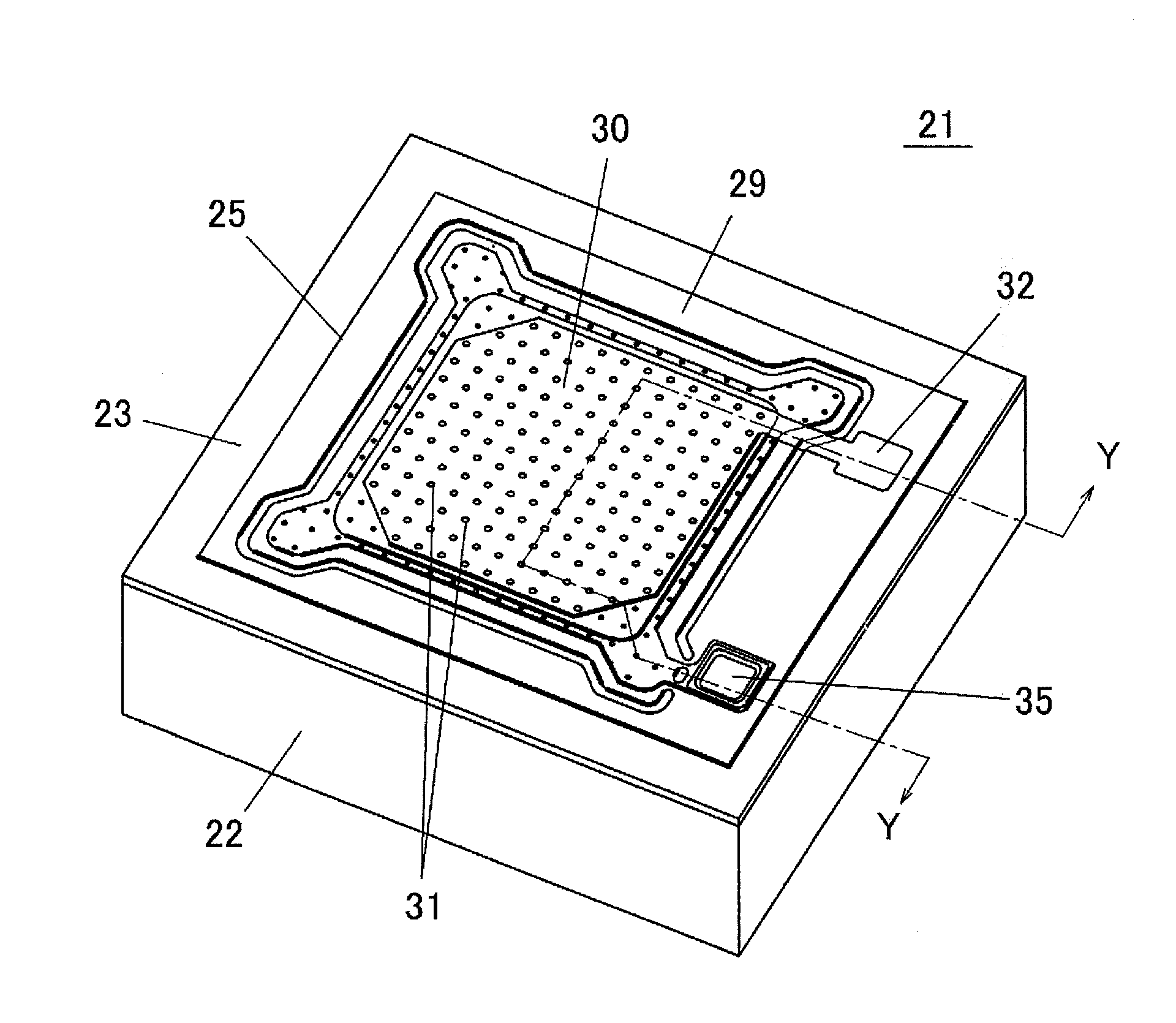
[0081]A first embodiment of the invention will be described with reference to FIGS. 5 to 13. FIG. 5 is a perspective view illustrating an acoustic sensor 21 according to the first embodiment of the invention, FIG. 6 is an exploded perspective view thereof, and FIG. 7 is a sectional view taken on a line Y-Y of FIG. 5.

[0082]The acoustic sensor 21 is of a capacitance type. In the acoustic sensor 21, a vibrating electrode plate 24 is provided on an upper surface of a silicon substrate 22 with an insulating coating 23 interposed therebetween, and a counter electrode plate 25 is provided on the vibrating electrode plate 24 with a micro gap (air gap) interposed therebetween.

[0083]A prismatic through-hole 26 or a truncated-pyramid recess is provided in the silicon substrate 22. The prismatic through-hole 26 is illustrated in the drawing. The silicon substrate 22 has a size of 1 to 1.5 mm square (can be formed smaller than this size) in a planar view, and the silicon substrat...

Example

Second Embodiment

[0105]An acoustic sensor according to a second embodiment will be described with reference to FIGS. 14 to 17. Because a structure of the acoustic sensor according to the second embodiment is substantially similar to the structure of the acoustic sensor 21 according to the first embodiment, the entire structure and description thereof are not provided.

[0106]The acoustic sensor of the second embodiment differs mainly from the acoustic sensor of the first embodiment in the shape of the vibrating electrode plate 24 and the arrangement of the projections 36. These different points will be described below.

[0107]FIG. 14 is a view illustrating a positional relationship among the vibrating electrode plate 24, the acoustic perforations 31, and the projections 36 in the second embodiment, when viewed from a direction perpendicular to the vibrating electrode plate 24. The vibrating electrode plate 24 has a circular disc shape, and a cylindrical through-hole or a truncated-cone ...

Example

Third Embodiment

[0113]FIG. 18 is a view illustrating a positional relationship among the vibrating electrode plate 24, the acoustic perforations 31, and the projections 36, according to a third embodiment, when viewed from a direction perpendicular to the vibrating electrode plate 24. FIG. 19 is a partially enlarged view illustrating the counter electrode plate 25 according to the third embodiment. In this embodiment, the projections 36 are brought close to the acoustic perforations 31 or are brought into contact with the acoustic perforations 31.

[0114]In the first and second embodiments, as illustrated in FIG. 21, the projection 36 is provided in the center of the region surrounded by the acoustic perforations 31. Therefore, the projection 36 is located far away from any of the acoustic perforations 31. When water 37 invading into the micro gap between the vibrating electrode plate 24 and the counter electrode plate 25 evaporates from the acoustic perforations 31, the water 37 rema...


PUM


Abstract

A vibrating electrode plate 24 that senses a sound pressure faces a counter electrode plate 25 to constitute a capacitance type acoustic sensor. In the counter electrode plate 25, acoustic perforations 31 are opened in order to pass vibration, and plural projections 36 are provided on a surface facing the vibrating electrode plate 24. An interval between the projections 36 is decreased in a region where the vibrating electrode plate 24 has high flexibility to easily generate local sticking with the counter electrode plate 25. The interval between the projections 36 is increased in a region where the vibrating electrode plate 24 has low flexibility to hardly generate local sticking with the counter electrode plate 25. The projections thus arranged prevent firm fixing of the vibrating electrode plate to the counter electrode plate and interruption of vibration of the vibrating electrode plate.

Description

TECHNICAL FIELD[0001]The present invention relates to an acoustic sensor, particularly to an acoustic sensor that detects a sound pressure propagating through gas or liquid, that is, acoustic vibration.BACKGROUND ART[0002]Japanese Unexamined Patent Publication No. 2006-157863 (Patent Document 1) discloses an acoustic sensor as one example.[0003]This acoustic sensor has a structure in which a vibrating electrode plate (movable electrode) and a counter electrode plate (fixed electrode) face each other with a micro gap (air gap) provided therebetween. Because the vibrating electrode plate is formed by a thin film having a thickness of about 1 μm, when the vibrating electrode plate receives a sound pressure, the vibrating electrode plate vibrates microscopically in response to vibration of the sound pressure. A gap between the vibrating electrode plate and the counter electrode plate changes when the vibrating electrode plate vibrates. Therefore, acoustic vibration is detected by detect...

Claims


Application Information

Patent Timeline
IPC IPC(8): G01H11/00
CPCG01H11/06H04R19/005H04R19/04G01H3/00
Inventor KASAI, TAKASHIWAKAO, KAZUTOSHIMATSUO, TAKESHIONISHI, TAKAYOSHITAKAHASHI, AKANE
Owner MMI SEMICON CO LTD
Why Eureka
Try Eureka