Method for manufacturing pipe-lining material

a manufacturing method and technology for pipe lining, applied in the field of pipe lining materials, can solve the problems of inability to uniformly heat-fuse tubes to tubular resin absorbent materials, inability to provide reliable linings, and inability to meet the requirements of pipe linings, etc., to achieve high-quality pipe lining materials, simple method, efficient heat-fusing

Inactive Publication Date: 2010-07-15
KAZU CHEM
View PDF4 Cites 3 Cited by
  • Summary
  • Abstract
  • Description
  • Claims
  • Application Information

AI Technical Summary

Benefits of technology

[0011]In the present invention, the heater is wound in close contact with the external peripheral surface of the tube that coves the tubular resin absorbent material. The tube and the tubular resin absorbent material are then heated by energizing the heater, so that the tube is heat-fused to the tubular resin absorbent material. Therefore, a mechanism for moving the tube and the tubular resin absorbent material is not required, and the tube can be uniformly heat-fused to the tubular resin absorbent material without generating heating non-uniformities, thereby manufacturing a high-quality pipe-lining material in a simple manner.
[0012]In the present invention, the tube and the tubular resin absorbent material can be heated without waste, and the tube can be efficiently heat-fused to the tubular resin absorbent material using a small amount of power because the heater is wound in close contact with the external peripheral surface of the tube.

Problems solved by technology

Without such movement, the distance from the heater to the tube and the tubular resin absorbent material differs in the upper part and the lower part of the furnace, so that non-uniformities are generated in heating and thereby the tube cannot be uniformly heat-fused to the tubular resin absorbent material.
When heat-fusion is insufficient, there is a problem that the resin impregnated in the tubular resin absorbent material is not adequately cured and thereby reliable lining becomes unavailable.
These cause another problem that wasteful heating and power consumption is inevitable.

Method used


Image

  • Method for manufacturing pipe-lining material
  • Method for manufacturing pipe-lining material
  • Method for manufacturing pipe-lining material

Examples


Embodiment Construction

[0016]Now, referring to the drawings, description is made about embodiments of the present invention. The description is herein made as regards a method for manufacturing a pipe-lining material used to line a sewage pipe as an existing pipe. However, the present invention is not limited to this case, but can be applied to other cases in which the method for manufacturing a pipe-lining material is used to line a clean water pipe, an agricultural water pipe, or the like.

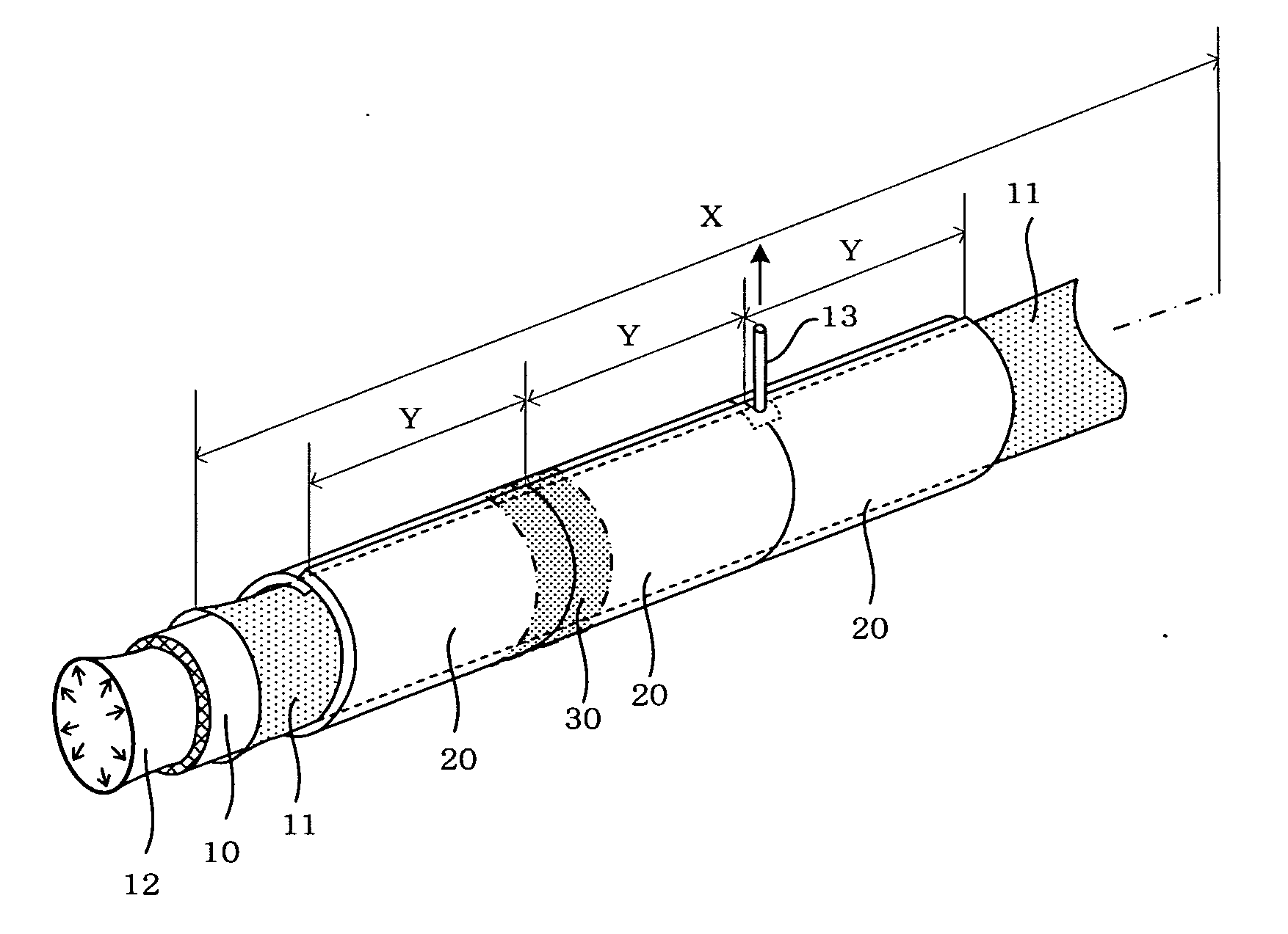
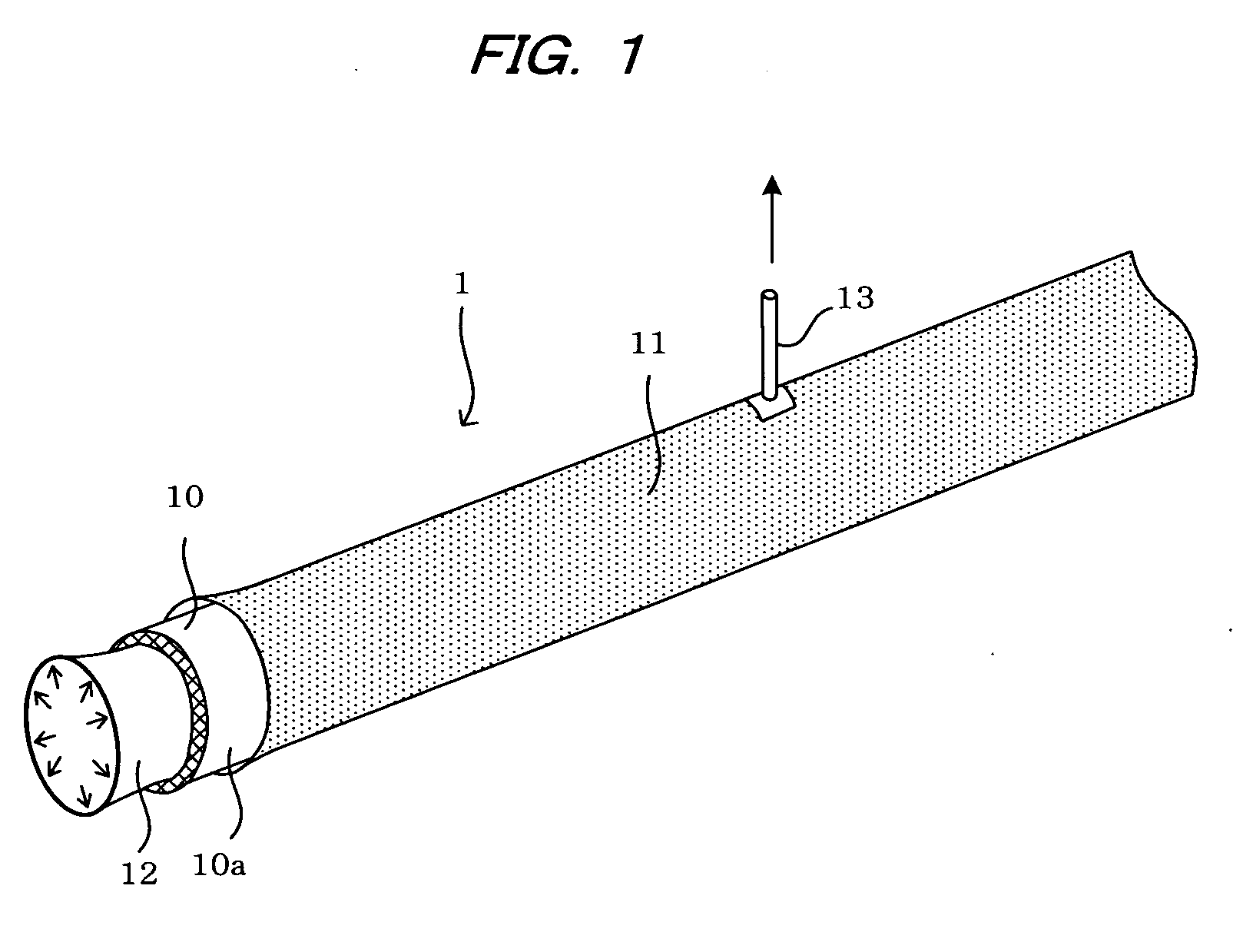
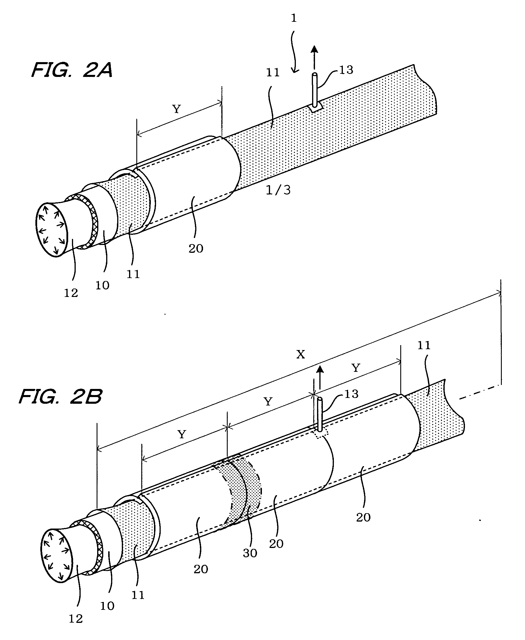
[0017]FIG. 1 shows a process for manufacturing a pipe-lining material used to repair or rehabilitate an existing pipe. A pipe-lining material 1 comprises a soft tubular resin absorbent material 10 whose external peripheral surface 10a is covered with a soft tube 11 composed of polyethylene, polypropylene, nylon, vinyl chloride, or another highly airtight plastic film.

[0018]The tubular resin absorbent material 10 is composed of a matte, a woven, or a nonwoven using polyamide, polyester, polypropylene, or another plastic...


PUM

PropertyMeasurementUnit
circumferenceaaaaaaaaaa
lengthaaaaaaaaaa
air pressureaaaaaaaaaa

Abstract

A method is proposed for manufacturing a pipe-lining material comprising a tubular resin absorbent material covered with a tube comprised of an airtight plastic film. The tubular resin absorbent material is inserted into the tube, expanded in a columnar shape, and brought into close contact with the internal peripheral surface of the tube. A heater is wound in close contact with the external peripheral surface of the tube thus expanded. The tube and the tubular resin absorbent material are heated by energizing the heater, and the tube is thereby heat-fused to the tubular resin absorbent material. With such a method, a mechanism for moving the tube and the tubular resin absorbent material is not required. In addition, since heat non-uniformities are not generated, the tube can be uniformly heat-fused to the tubular resin absorbent material, thereby enabling a high-quality pipe-lining material to be manufactured.

Description

BACKGROUND OF THE INVENTION[0001]1. Field of the Invention[0002]The present invention relates to a method for manufacturing a pipe-lining material for lining a deteriorated existing pipe.[0003]2. Description of the Related Art[0004]Pipe channel lining methods are used for repairing an existing pipe without unearthing the existing pipe in the case that the underground existing pipe such as a clean water pipe, sewage pipe, or the like has deteriorated. With this method, the pipe-lining material composed of a tubular resin absorbent material in which a thermosetting resin has been impregnated is inserted into an existing pipe by eversion or drawing, and is expanded by air pressure or the like and held in a state that the pipe-lining material is pressed against the internal peripheral surface of the existing pipe. In this state, the pipe-lining material is heated, and the thermosetting resin impregnated in the tubular resin absorbent material is cured to line the existing pipe (e.g., Ja...

Claims


Application Information

Patent Timeline
Patent Type & Authority Applications(United States)
IPC IPC(8): B65H81/00
CPCB29C35/02H05B2203/014B29C65/18B29C65/30B29C66/52272B29C66/634B29C66/721B29C66/82661B29C2791/006B29K2023/06B29K2023/12B29K2027/06B29K2031/00B29K2063/00B29K2067/00B29K2077/00B29K2101/10B29K2105/06B29K2105/0845B29K2105/0854B29K2105/246B29K2309/08B29K2995/0067B29L2009/00B29L2023/006B29L2031/605B32B37/04F16L55/1654F16L55/1656H05B3/34H05B2203/003H05B2203/005B29C35/08B29C66/7212B29C66/72143B29C66/7394B29C66/72141B29C66/71B29C66/73921B29C66/1122B29K2277/00B29K2301/00B29C63/26F16L55/16
Inventor KAMIYAMA, TAKAOKANETA, KOJIFUJII, KENJIUENO, MASAO
Owner KAZU CHEM
Why Eureka
Try Eureka