Tool holder for a power tool, particularly for a chisel hammer and/or rotary hammer

a tool holder and power tool technology, applied in the field of tool holders, can solve the problems of accelerated wear of components of the locking device, adversely affecting the load distribution, etc., and achieve the effects of increasing the locking action, enhancing the safety of use, and prolonging the service life of the locking devi

Active Publication Date: 2010-07-15
ROBERT BOSCH GMBH
View PDF27 Cites 10 Cited by
  • Summary
  • Abstract
  • Description
  • Claims
  • Application Information

AI Technical Summary

Benefits of technology

[0007]A tool holder on the order of the main claim of the invention has a tool receptacle as well as a locking device with two locking elements, one blocking element and one restoring element. The two locking elements, in a structurally simple and economical way, enhance the safety of use and lengthen the service life of the locking device. The restoring element of the invention upon insertion of the shaft of the tool insert into the tool receptacle exerts different forces on the locking elements. As a result, it can be attained that despite the increased locking action by the two locking elements, the user need not expend increased force when changing tool inserts.
[0008]By means of the provisions recited in the dependent claims, advantageous refinements of and improvements to the characteristics recited in the main claim are obtained.
[0009]By means of an axial contact face located on the inner jacket face of the blocking element, the radial motion of the locking elements is limited effectively and at the same time economically.
[0010]An axially displaceable restoring element allows an expanded radial motion of the locking elements. As a result, especially sturdy unlocking of the locking device is attained for the sake of inserting the tool insert.
[0011]A preferred embodiment of the restoring element has an elastic element and a holding element. The elastic element generates a restoring force. While the holding element carries the restoring force onward to the blocking element and the locking elements. By means of this construction, especially economical production of the restoring element is attained.
[0012]In an especially economical way, the elastic element can be embodied as a spring.

Problems solved by technology

Because of the constantly increasing hammering power of power tools, the thus-increasing loads on the locking element cause accelerated wear to components of the locking device—particularly of the locking element.
Because of the sudden type of load, the vibratable locking device is additionally caused to vibrate, and the vibration adversely affects the load distribution.

Method used


Image

  • Tool holder for a power tool, particularly for a chisel hammer and/or rotary hammer
  • Tool holder for a power tool, particularly for a chisel hammer and/or rotary hammer
  • Tool holder for a power tool, particularly for a chisel hammer and/or rotary hammer

Examples


Embodiment Construction

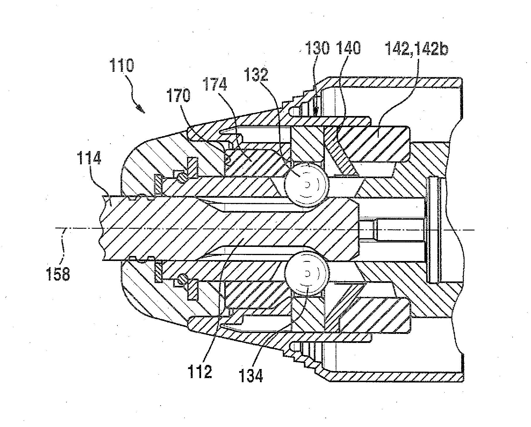
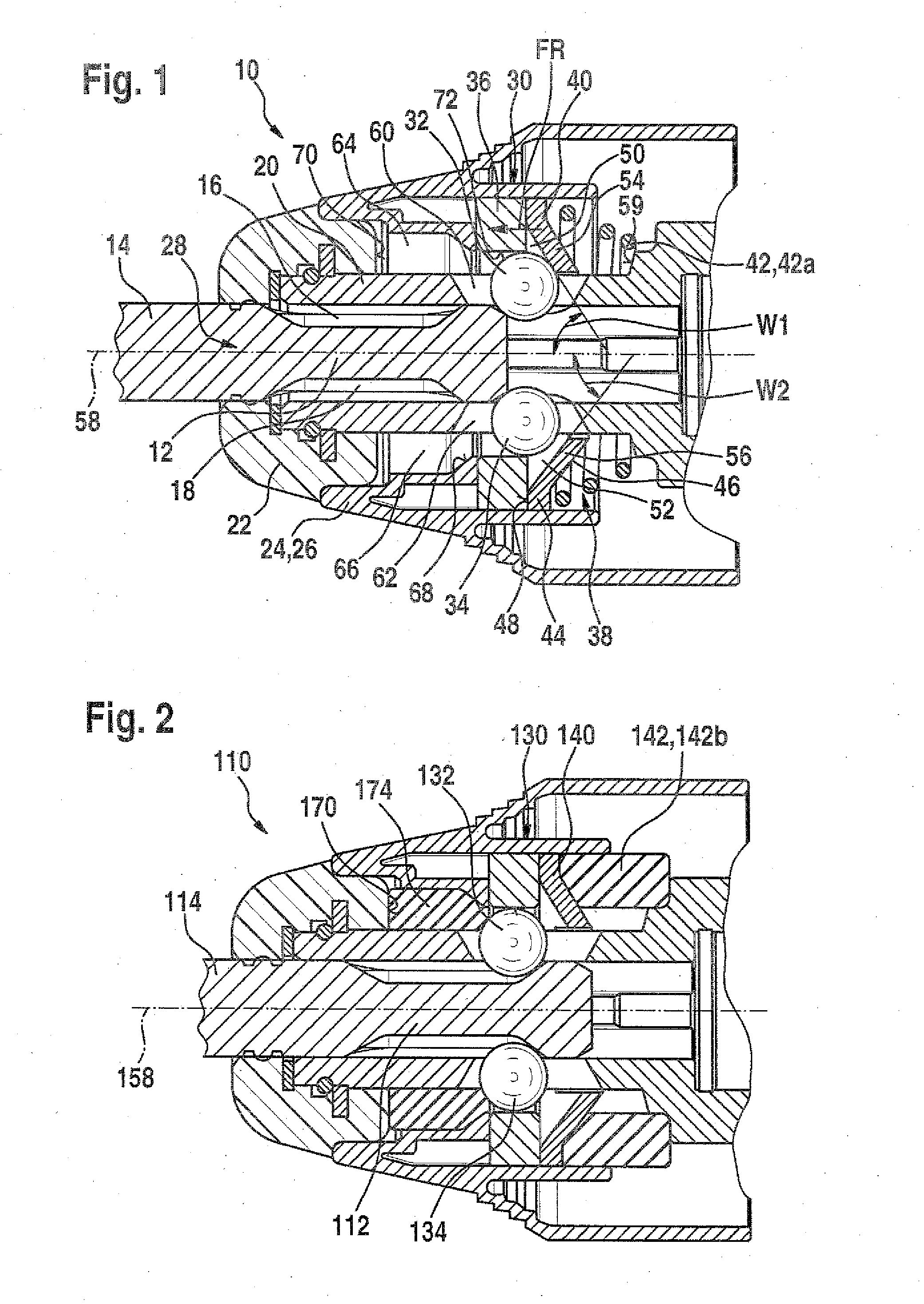
[0025]The tool holder 10 according to the invention, shown in FIG. 1, of a chisel hammer and / or rotary hammer is intended for receiving a cylindrical shaft 12 of a tool insert 14. In this tool insert 14, the cylindrical shaft 14 has two diametrically opposed detent indentations 16, 18 in its circumferential surface.

[0026]The tool holder 10 includes a tool receptacle 20, which is tubular in its interior; a protective cap 22; and an actuation element 24. The actuation element 24 is preferably embodied as an actuation sleeve 26. The tool receptacle 20 serves to receive the cylindrical shaft 12, inserted through an insertion opening 28 on the face end of the tool holder 10. The tool holder 10 furthermore has a locking device 30 for the cylindrical shaft 12 of the tool insert 14.

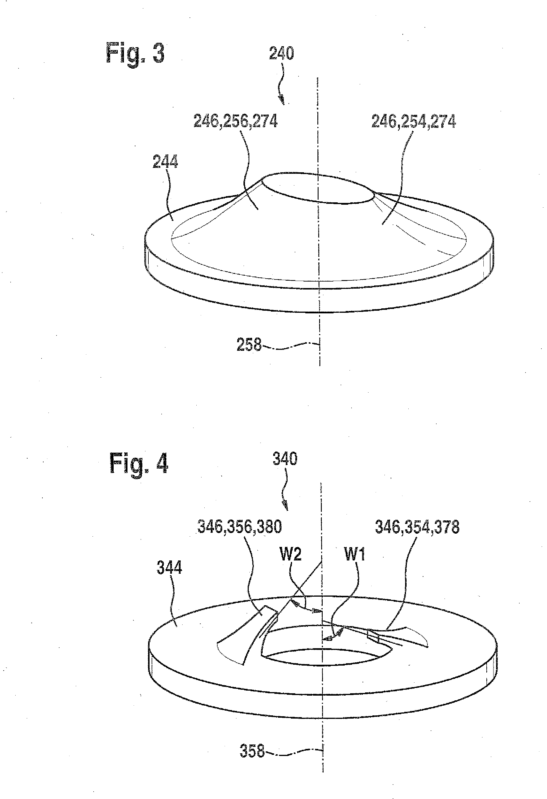
[0027]In accordance with the invention, the locking device 30 includes two locking elements 32, 34, one blocking element 36, and one restoring element 38. In a preferred embodiment, the locking elements 32, 34 ar...


PUM

PropertyMeasurementUnit
forcesaaaaaaaaaa
axial displacementaaaaaaaaaa
restoring forceaaaaaaaaaa

Abstract

The invention relates to a tool holder for an electric tool, particularly for a chisel hammer and/or drill hammer. A tool receptacle is provided for receiving a cylindrical shaft of an insertion tool introduced through an insertion opening. The cylindrical shaft has at least two diametrically opposed detent depressions on its circumferential surface. The tool holder further has a locking device having at least one locking element, at least one blocking element and at least one restoring element. According to the invention, the locking device has at least two locking elements. Upon insertion of the cylindrical shaft of the insertion tool, the restoring element applies different forces to the locking elements of the locking device.

Description

PRIOR ART[0001]The invention relates to a tool holder, in particular for a chisel hammer and / or rotary hammer, as generically defined by the preamble to the main claim. For receiving and axially locking drilling or chiseling tools in percussively operated power tools, various tool holders are known. Tool holders of the kind described among other places in German Patent Disclosure DE 10 2005 015100 A1 have a tool receptacle for receiving a cylindrical shaft, introduced through an insertion opening, of a tool insert. In the cylindrical circumferential surface of the shaft, two diametrically opposed detent indentations are provided. The tool holder also has a locking device, which includes a locking element, a blocking element, and a restoring element.[0002]Locking of the tool insert in the tool receptacle is done automatically upon insertion. Here the locking element is displaced axially, counter to the restoring element acted upon by restoring force—usually implemented by a prestress...

Claims


Application Information

Patent Timeline
Patent Type & Authority Applications(United States)
IPC IPC(8): B25D17/08B23B31/16
CPCY10T279/17811B25D17/24B25D2250/285Y10T279/17461Y10T279/17076B25D17/088Y10T279/17145Y10T279/17094Y10T279/17761B25D2217/0042B25D2250/371B25D2222/57B25D2250/385B25D2217/0049
Inventor BRAUN, WILLYKOEPF, CHRISTIAN
Owner ROBERT BOSCH GMBH
Why Eureka
Try Eureka