Microbubble therapy method and generating apparatus

a micro-bubble and bubble technology, applied in the direction of flow mixers, genital massage, water/sewage treatment by irradiation, etc., can solve the problems of physical size and configuration, process cost, and inability to facilitate efficient and practical use, and achieve the effect of enhancing the visual experience of a user

Active Publication Date: 2010-07-15
AMERICAN IND BRANDS LLC
View PDF36 Cites 52 Cited by
  • Summary
  • Abstract
  • Description
  • Claims
  • Application Information

AI Technical Summary

Benefits of technology

[0017]In another aspect the methods of micro bubble therapy may include a step of providing air bubbles larger than the micro bubbles. In yet another aspect, the methods of micro bubble therapy may include a step of providing illumination to the fluid to enhance the visual experience of a user and provide chromatherapic benefits. In another aspect, methods of micro bubble therapy may include a step of providing an aromatic gas, such as a scent, in the saturated gas used to create the micro bubbles. In another aspect, the micro bubble method includes sanitizing a fluid, such as water, in a bathtub well or liquid carrier well.

Problems solved by technology

The old devices for bubble generating apparatuses that produce micro bubbles have drawbacks which do not allow for the efficient and practical use.
This process is costly when a large number of micro bubbles is to be generated.
The design characteristics preclude it from being used with fluid dispensing fittings because the physical size and configuration would not be practical.
In patent numbers U.S. Pat. No. 6,293,529 and U.S. Pat. No. 4,556,523, the micro bubbles could not practically or efficiently be used with typical fluid dispensing fittings such as hydrotherapy jets, shower heads, and liquid nozzles.
This is a drawback because debris or other contaminates that are present in the liquid will eventually clog these small orifices.
This would require expensive prefiltering of the liquid prior to reaching the small orifices and screens or repeated and continuous cleaning of the micro bubble producing screens would be required to maintain a properly operating micro bubble generating apparatus.
This is not practical since it would be an unnecessary burden on the end user.
The clogging of the small orifices and screens may also be detrimental to the system employing the bubble generating apparatus.
The blockage could cause excessive back pressure resulting in premature wear on the systems components.

Method used


Image

  • Microbubble therapy method and generating apparatus
  • Microbubble therapy method and generating apparatus
  • Microbubble therapy method and generating apparatus

Examples


Embodiment Construction

[0049]Overview

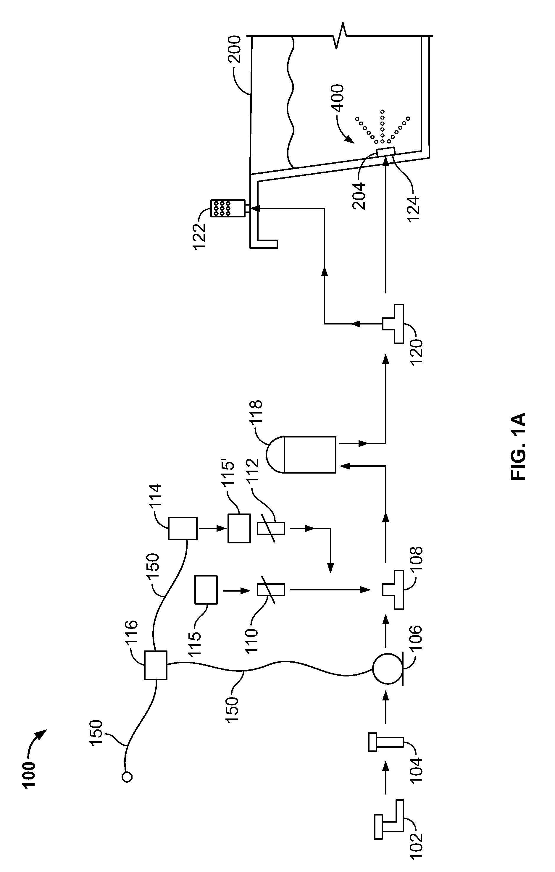
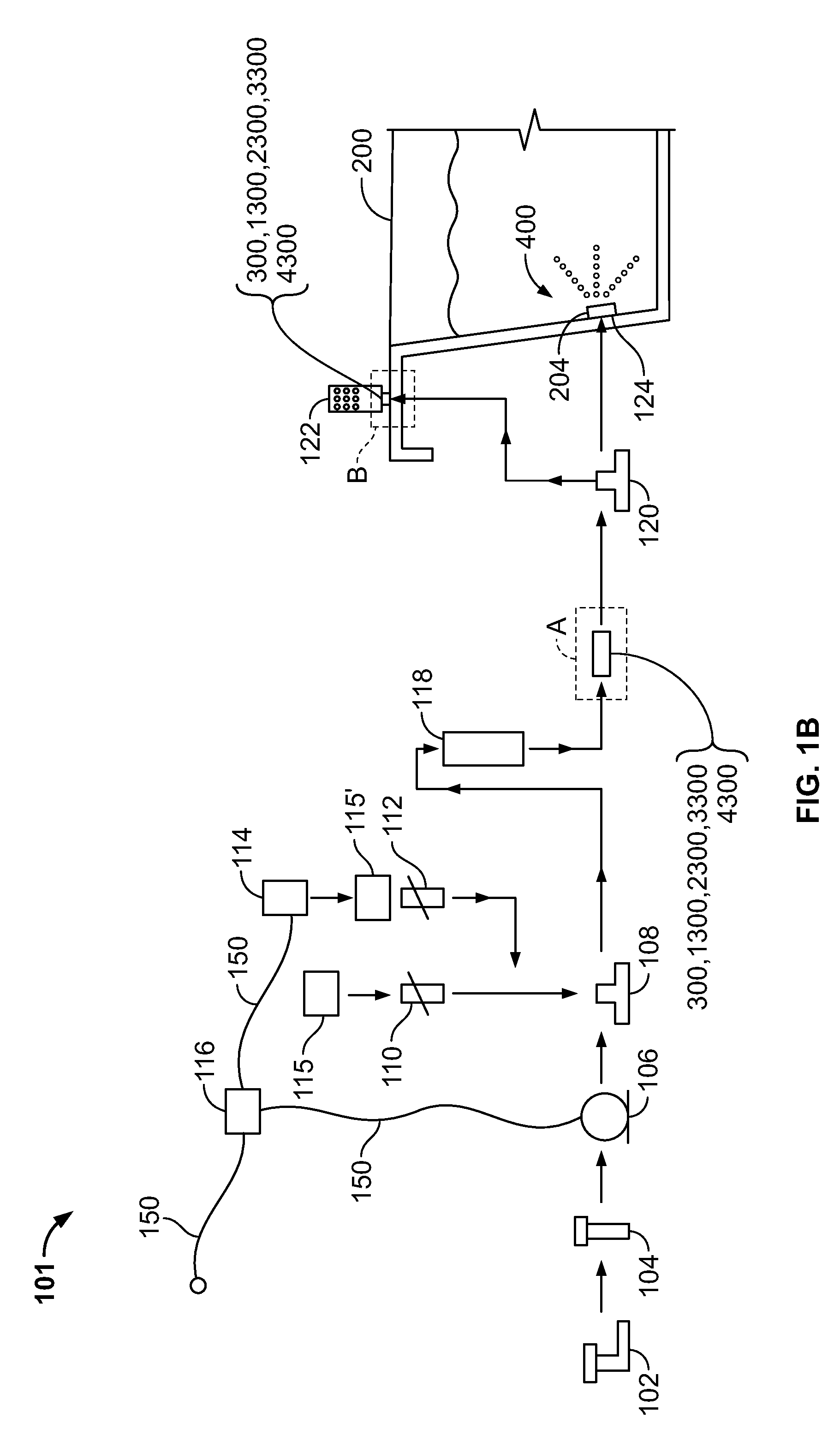
[0050]Inventive aspects pertain to a bubble generating apparatus, such as an apparatus for micro bubble generation. It is understood that other embodiments may be utilized and structural and functional modifications may be made without departing from the scope of the present invention.

[0051]General

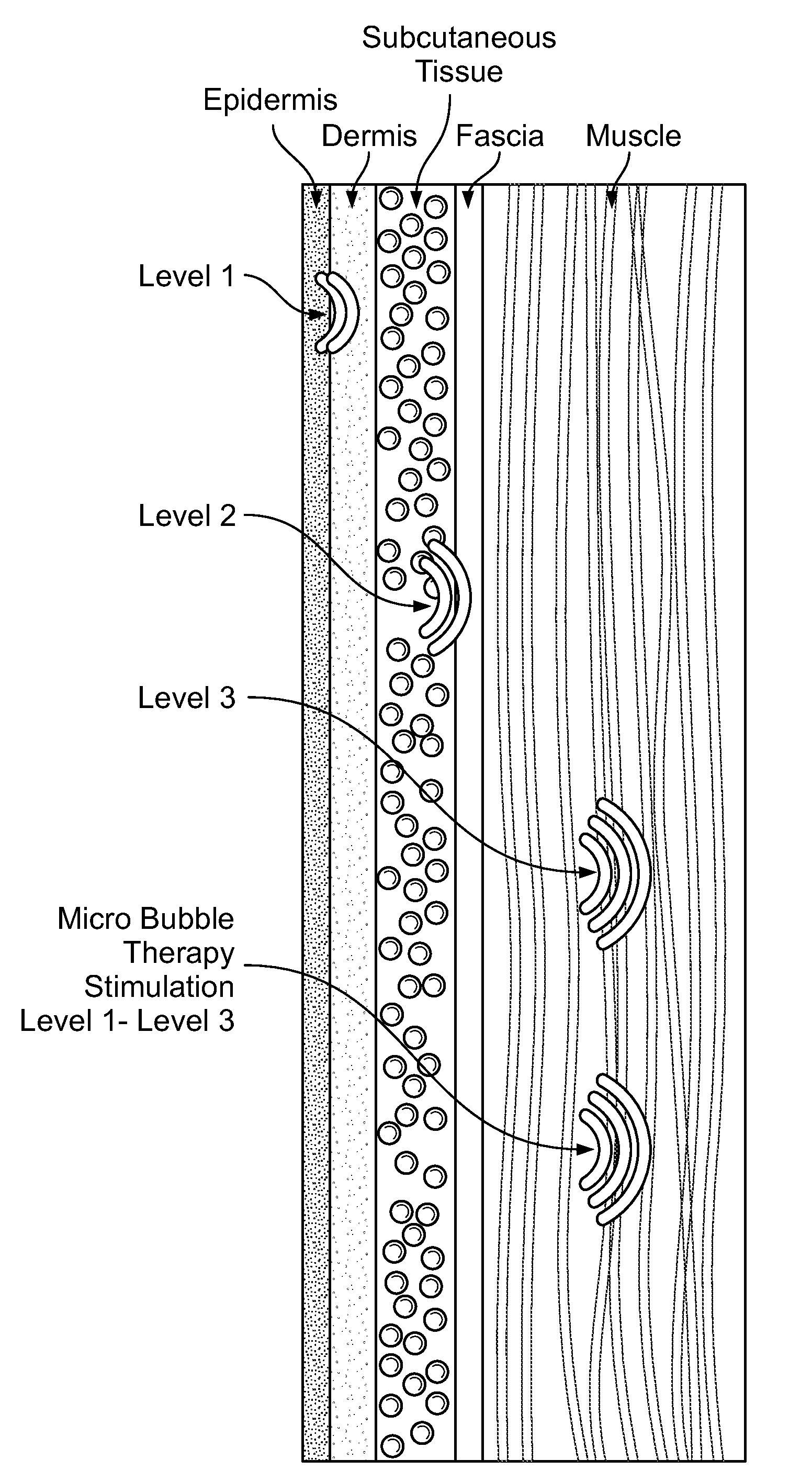
[0052]As used herein, the term “micro bubbles” are generally referred to gas bubbles disposed within a liquid. One such liquid is water. A micro bubble generally measure approximately less than 100 microns or 0.004 inches in diameter as compared to a typical gas bubble in conventional whirlpool, air bath, or, air whirlpool bath that is approximately 0.060 inches to 0.125 inches in diameter.

[0053]The micro bubbles may comprise numerous gases, including but not limited to, oxygen, ambient air, or ozone or other therapeutic gases or scents / gases for use during hydrotherapy. The micro bubbles can remain suspended in water for an extended period of time. Gradually, the gas within ...


PUM

PropertyMeasurementUnit
diameteraaaaaaaaaa
diameteraaaaaaaaaa
diameteraaaaaaaaaa

Abstract

A micro bubble generating system includes a shell having a well for retaining a first liquid to immerse an object. A micro bubble apparatus is provide to the shell for providing a pressurized mixture of a second liquid and a dissolved gas into the well so as to create a plurality of micro bubbles within the first liquid for engaging the object. One method of using micro bubbles includes providing a fluid mixture, including a saturated gas, to a fluid chamber connected a fitting; and producing a plurality of micro bubbles into a fluid. Another method of using micro bubbles includes providing a fluid mixture, including a saturated gas, into an air entrapment chamber; and producing a plurality of micro bubbles into a fluid.

Description

BACKGROUND[0001]The technology pertains generally to a bubble generating apparatus, in particular a method and apparatus for micro bubble generation and therapy.[0002]The old devices for bubble generating apparatuses that produce micro bubbles have drawbacks which do not allow for the efficient and practical use. One known method for producing micro bubbles is to procure electrolysis between two electrodes in the liquid, the micro bubbles being formed by a gas released by the electrolysis and appearing on one of the electrodes. This process is costly when a large number of micro bubbles is to be generated. The design characteristics preclude it from being used with fluid dispensing fittings because the physical size and configuration would not be practical.[0003]In patent numbers U.S. Pat. No. 6,293,529 and U.S. Pat. No. 4,556,523, the micro bubbles could not practically or efficiently be used with typical fluid dispensing fittings such as hydrotherapy jets, shower heads, and liquid...

Claims


Application Information

Patent Timeline
Patent Type & Authority Applications(United States)
IPC IPC(8): A61H9/00B01F3/04C02F1/32
CPCA01K13/001A01K63/042A61H7/003A61H33/02A61H33/6036A61H2033/0029A61H33/60A61H2033/0083A61H2201/102B01F3/0446B01F5/0661D06F35/002A61H2033/0079B01F23/232B01F25/44B01F23/2326
Inventor CUNNINGHAM, JEFFREY L.JACKSON, ERIC EUGENEJACUZZI, REMO C.
Owner AMERICAN IND BRANDS LLC
Why Eureka
Try Eureka