Video Projection System Mounting Panel

a technology for mounting panels and projection systems, applied in the direction of loudspeakers, machine supports, instruments, etc., can solve the problems of difficult to harmonize with the aesthetic environment of a presentation room, require a customized list of parts, and require a large number of parts, so as to reduce installation work and improve aesthetics. , the effect of pleasant appearan

Inactive Publication Date: 2010-07-22
OLDS DEAN W
View PDF7 Cites 4 Cited by
  • Summary
  • Abstract
  • Description
  • Claims
  • Application Information

AI Technical Summary

Benefits of technology

[0008]The present invention is a mounting panel for attaching a projection device to an overhead structure includes a panel attachable to the projection device and a panel attachable to a number of accessories. The mounting panel is attachable to a plurality of speakers, an amplifier, and a power rough in creating one ceiling installed video projection device. The mounting panel for attaching a projection device reduces installation work in a standard grid ceiling and provides a pleasant appearance for the projector and accessories.

Problems solved by technology

The shortcoming of these systems is that they are labor intensive to install and require a customized list of parts for each installation.
The channels, however, result in a rather bulky device that may be difficult to harmonize with the aesthetic environment of a presentation room.
Other prior devices such as the low-profile LCD projector mount disclosed in U.S. Pat. No. 6,042,068, offer a relatively more compact mount arrangement, but still offer only a limited range of projector mounting positions and have no accommodations for the mounting of additional accessories in a standard grid ceiling.

Method used


Image

  • Video Projection System Mounting Panel
  • Video Projection System Mounting Panel
  • Video Projection System Mounting Panel

Examples


Embodiment Construction

[0016]In the following are detailed descriptions of the invention of exemplary embodiments. These embodiments are described in sufficient detail to enable those skilled in the art to practice the invention, but other embodiments may be utilized and logical, mechanical, electrical, and other changes may be made without departing from the scope of the present invention. The following detailed description is, therefore, not to be taken in a limiting sense, and the scope of the present invention is defined only by the appended claims.

[0017]In the following description, numerous specific details are set forth to provide a thorough understanding of the invention. However, it is understood that the invention may be practiced without these specific details. In other instances, well-known structures and techniques known to one of ordinary skill in the art have not been shown in detail in order not to obscure the invention.

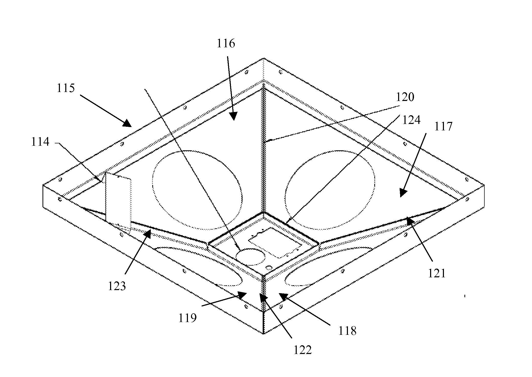
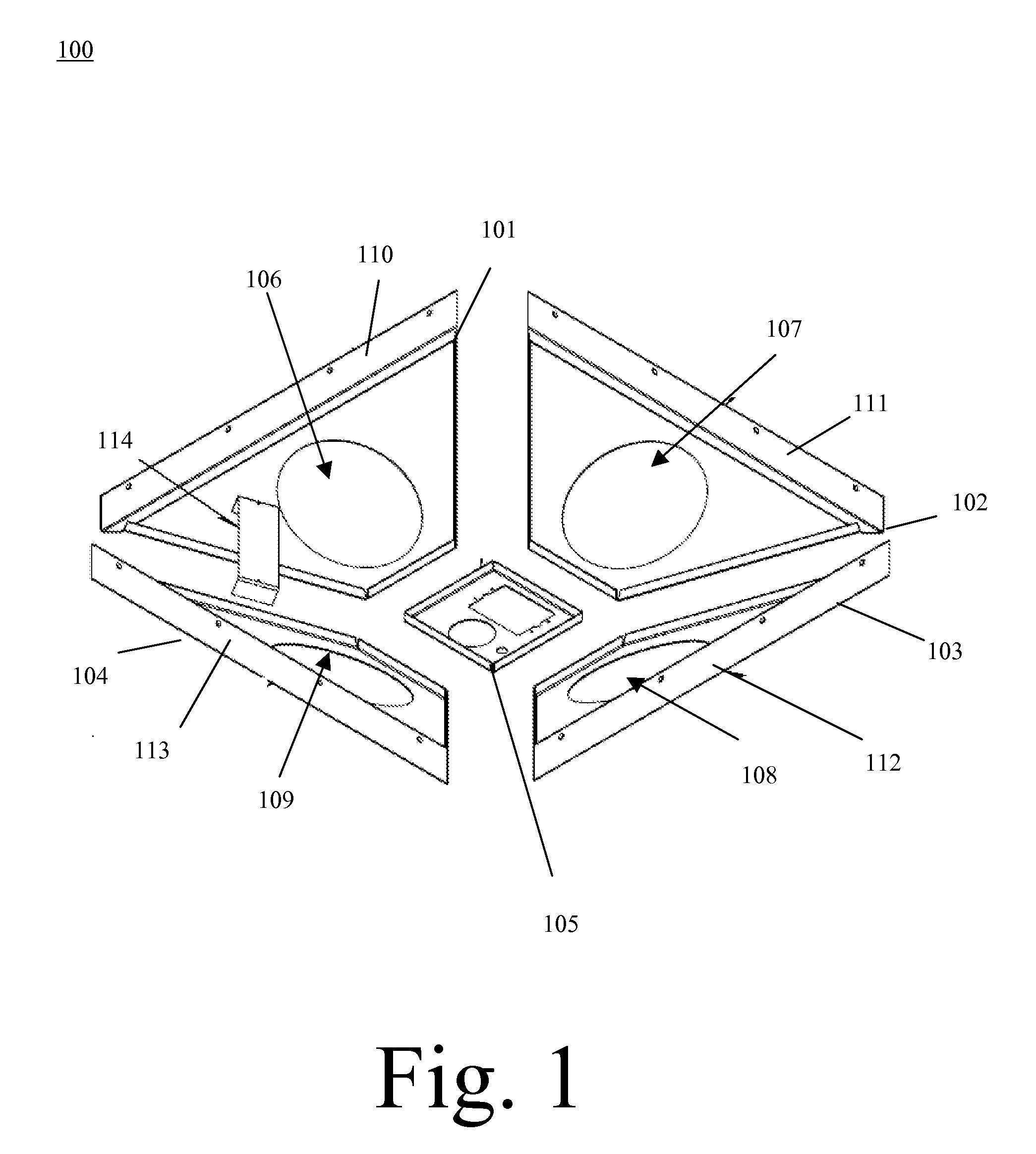
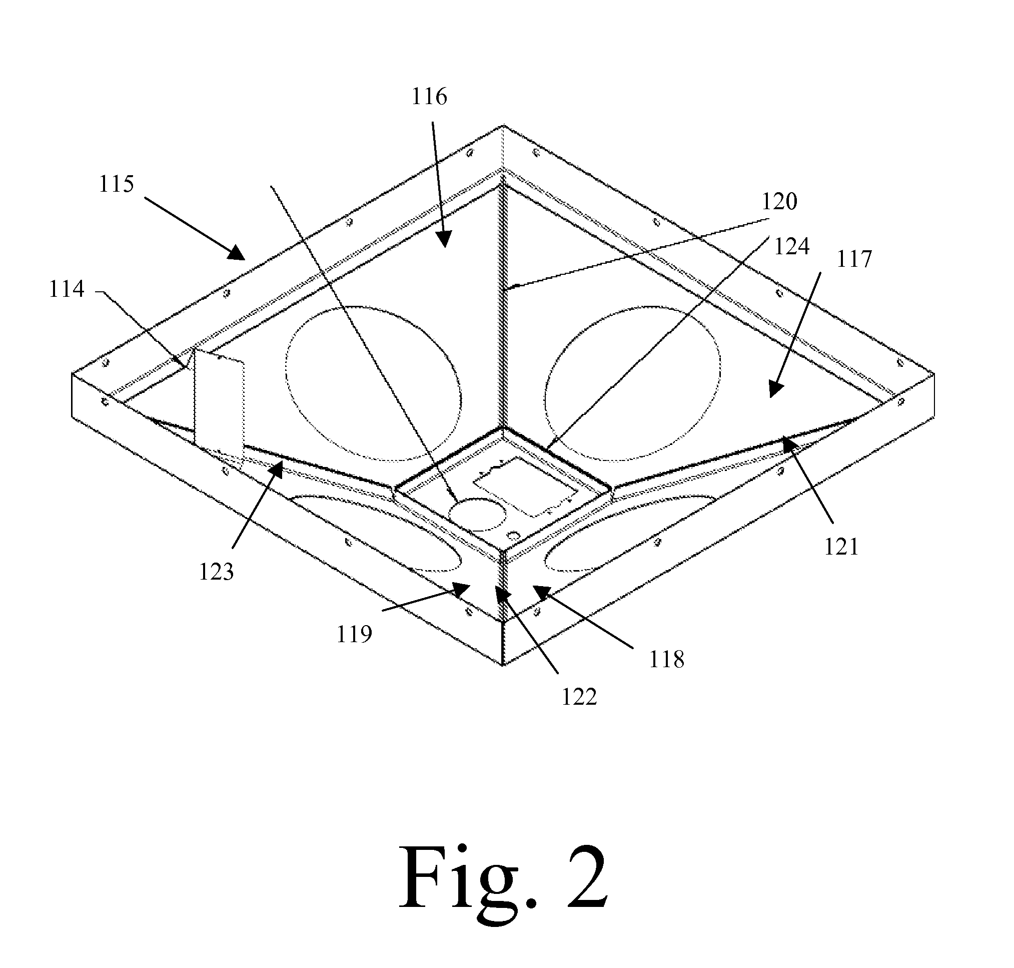
[0018]Now referring to FIG. 1 an exploded view of the components of th...


PUM


Abstract

A mounting panel for attaching a projection device to an overhead structure or standard grid ceiling includes a mounting panel attachable to a projection device and to a number of accessories. The mounting panel is attachable to a plurality of speakers, an amplifier, and a power rough in, creating one ceiling installed video projection device. The mounting panel for attaching a projection device reduces installation work in a standard grid ceiling and provides a pleasant appearance for the projector and accessories.

Description

CROSS REFERENCE TO RELATED APPLICATIONS[0001]This application claims priority from U.S. Provisional Patent Application Ser. No. 61 / 146,397, entitled “Video Projection System Mounting Panel”, filed on 22 Jan. 2009. The benefit under 35 USC §119(e) of the United States provisional application is hereby claimed, and the aforementioned application is hereby incorporated herein by reference.FEDERALLY SPONSORED RESEARCH[0002]Not ApplicableSEQUENCE LISTING OR PROGRAM[0003]Not ApplicableTECHNICAL FIELD OF THE INVENTION[0004]The present invention relates generally to video projection mounting systems. More specifically, the present invention relates to video projection system mounts combining speakers, projection mounts, and other accessories.BACKGROUND OF THE INVENTION[0005]Similar mounting systems known in the prior art require multiple different items in the ceiling to be mounted. The shortcoming of these systems is that they are labor intensive to install and require a customized list of...

Claims


Application Information

Patent Timeline
Patent Type & Authority Applications(United States)
IPC IPC(8): A47B81/06
CPCF16M11/04F16M11/22F16M13/02H04R2201/021G03B31/00H04R1/025G03B21/54
Inventor OLDS, DEAN W.
Owner OLDS DEAN W
Why Eureka
Try Eureka