
Two Stage Detection for Photographic Eye Artifacts

a technology of photographic eye artifacts and detection algorithms, applied in image data processing, color television, television systems, etc., can solve the problems of high computation and memory resources, detection algorithms are only able, and the face detection is not rotated in-plane or out-of-plane with respect to the image plane, etc., to achieve accurate image analysis and avoid disadvantages. general effects

Active Publication Date: 2010-07-22
FOTONATION LTD
View PDF102 Cites 0 Cited by
  • Summary
  • Abstract
  • Description
  • Claims
  • Application Information

AI Technical Summary

Benefits of technology

This approach enables near-instant red-eye correction during image acquisition, maintaining high detection accuracy and image quality, and reduces the need for post-processing, thereby enhancing user experience and minimizing resource constraints in embedded systems.

Problems solved by technology

In general, face-detection-based automatic redeye reduction techniques have high computation and memory resource requirements.
In addition, most of the face detection algorithms are only able to detect faces that are oriented in an upright frontal view.
These approaches generally do not detect faces that are rotated in-plane or out-of-plane with respect to the image plane.
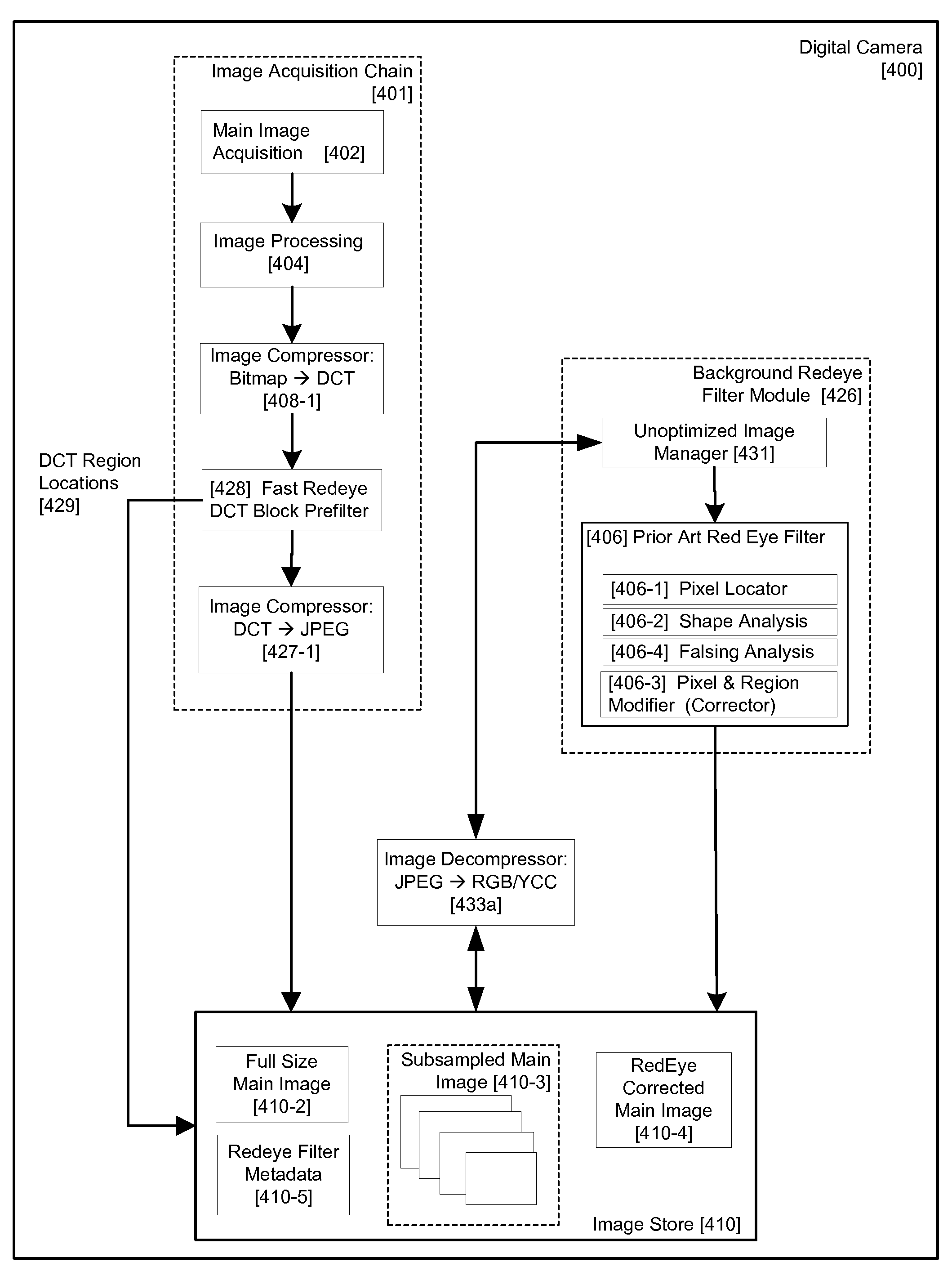
Within an image acquisition subsystem such as is embodied in typical digital cameras, a peak computing load and resource requirements occur around the time of image acquisition.
Such a redeye filter typically compromises its overall performance in terms of accuracy of detection of redeye defects and quality of image correction.
There can be drawbacks to this alternative approach, though.
First, images are displayed on the acquiring device, immediately after acquisition, with uncorrected redeye defects.
Second, when images are accessed in playback mode, there is a further delay while images are post-processed before an image can be displayed.
Both drawbacks would create a negative impression on end users.
Further, as most digital cameras store images using lossy compression techniques there can be additional disadvantages with respect to image quality as images are decompressed and recompressed in order to perform redeye detection and correction processes in playback or background modes.
Such loss of image quality may not become apparent until later when a user wishes to print an image and it is too late to reverse the process.
If redeye processing is delayed until the images are loaded onto another device, such as a desktop PC or printer, there can be further disadvantages.
First, meta-data relating to the acquiring device and its state at the time the image was acquired may not be available to the redeye filter process.

Method used


Image

  • Two Stage Detection for Photographic Eye Artifacts
  • Two Stage Detection for Photographic Eye Artifacts
  • Two Stage Detection for Photographic Eye Artifacts

Examples


Embodiment Construction

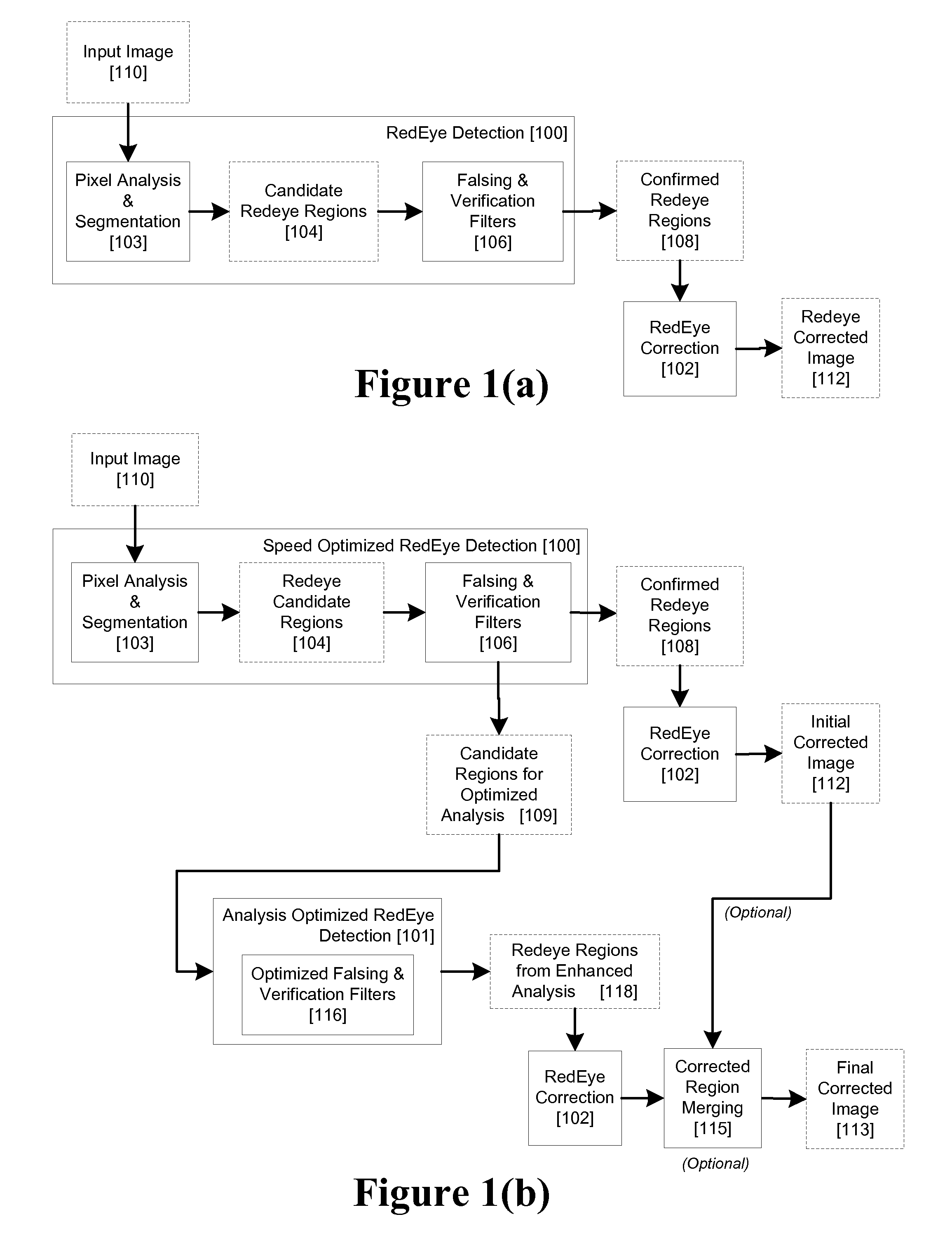
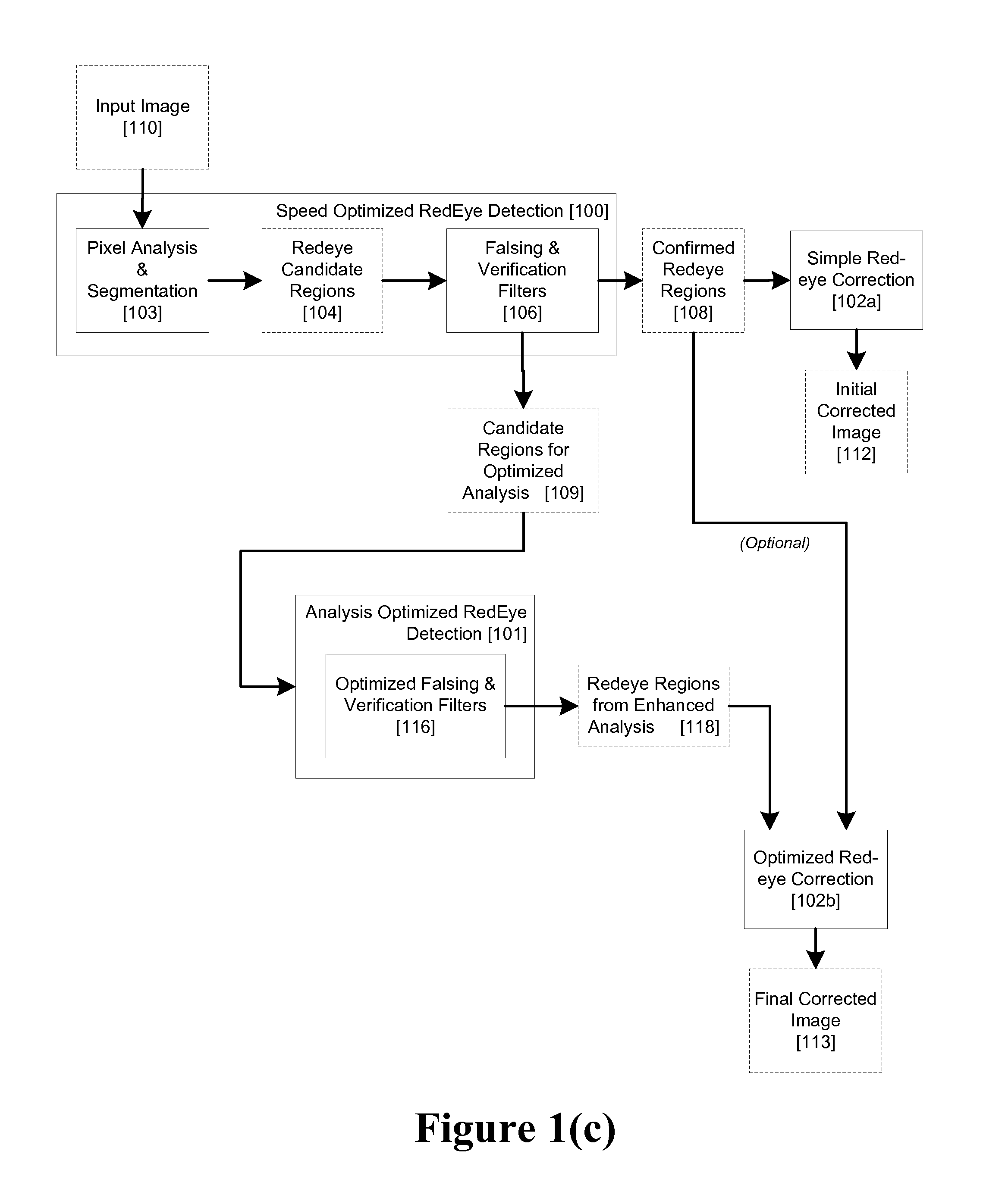
[0036]A red eye process in accordance with a preferred embodiment is illustrated in FIG. 1(b). An input image 110 is processed by a pixel analyzer 103, segmented into a set of candidate regions 104 and subsequently passed through a set of falsing & verification filters 106. these components form a speed optimized redeye detection filter 100 corresponding generally to the filter 100 of FIG. 1(a), except that in the embodiment illustrated at FIG. 1(b), filter 100 is modified so that candidate redeye regions which, instead of being ultimately classified as false positives, based on their size or probability being below a predetermined threshold are saved as candidate regions 109 for a subsequent optimized analysis 101.

[0037]Thus, in this embodiment the falsing & verification filters 106 generates a set of secondary candidate regions 109 in addition to the set of confirmed redeye regions 108. The set of secondary candidate regions may include members of the original candidate region set...


PUM


Abstract

An image acquisition device includes a first speed-optimized filter for producing a first set of candidate red-eye regions for an acquired image; and a second analysis-optimized filter for operating on the first set of candidate red eye regions and the acquired image.

Description

CROSS-REFERENCE TO RELATED APPLICATIONS[0001]This application is a continuation of U.S. patent application Ser. No. 11 / 282,954, filed Nov. 18, 2005, entitled, “Two Stage Detection for photographic Eye Artifacts”, by inventors Peter Corcoran, Eran Steinberg, Alexei Pososin, and Mihai Cuic; published as US 2007 / 0116379 on May 24, 2007.BACKGROUND[0002]1. Field of the Invention[0003]The present invention relates to digital image processing, and more particularly to a method and apparatus for detection and correction of red-eye defects and / or other artifacts in an acquired digital image.[0004]2. Description of the Related Art[0005]Redeye is the appearance of an unnatural reddish coloration of the pupils of a person appearing in an image captured by a camera with flash illumination. Redeye is caused by light from the flash reflecting off blood vessels in the person's retina and returning to the camera.[0006]A large number of image processing techniques have been proposed to detect and cor...

Claims


Application Information

Patent Timeline
Patent Type & Authority Applications(United States)
IPC IPC(8): H04N5/76
CPCG06K9/0061G06T2207/30216G06T7/90G06V40/193
Inventor CORCORAN, PETERSTEINBERG, ERANPOSOSIN, ALEXEICIUC, MIHAI
Owner FOTONATION LTD
Learn More