
System and method for optimizing network wireless communication resources

a network wireless communication and resource optimization technology, applied in data switching networks, frequency-division multiplexes, instruments, etc., can solve problems such as reducing the signal quality of users' base stations or cells, reducing the transmission power required for error-free communication, and reducing the signal quality of adjacent coverage areas or cells

Active Publication Date: 2010-07-22
INTEL CORP
View PDF20 Cites 67 Cited by
  • Summary
  • Abstract
  • Description
  • Claims
  • Application Information

AI Technical Summary

Benefits of technology

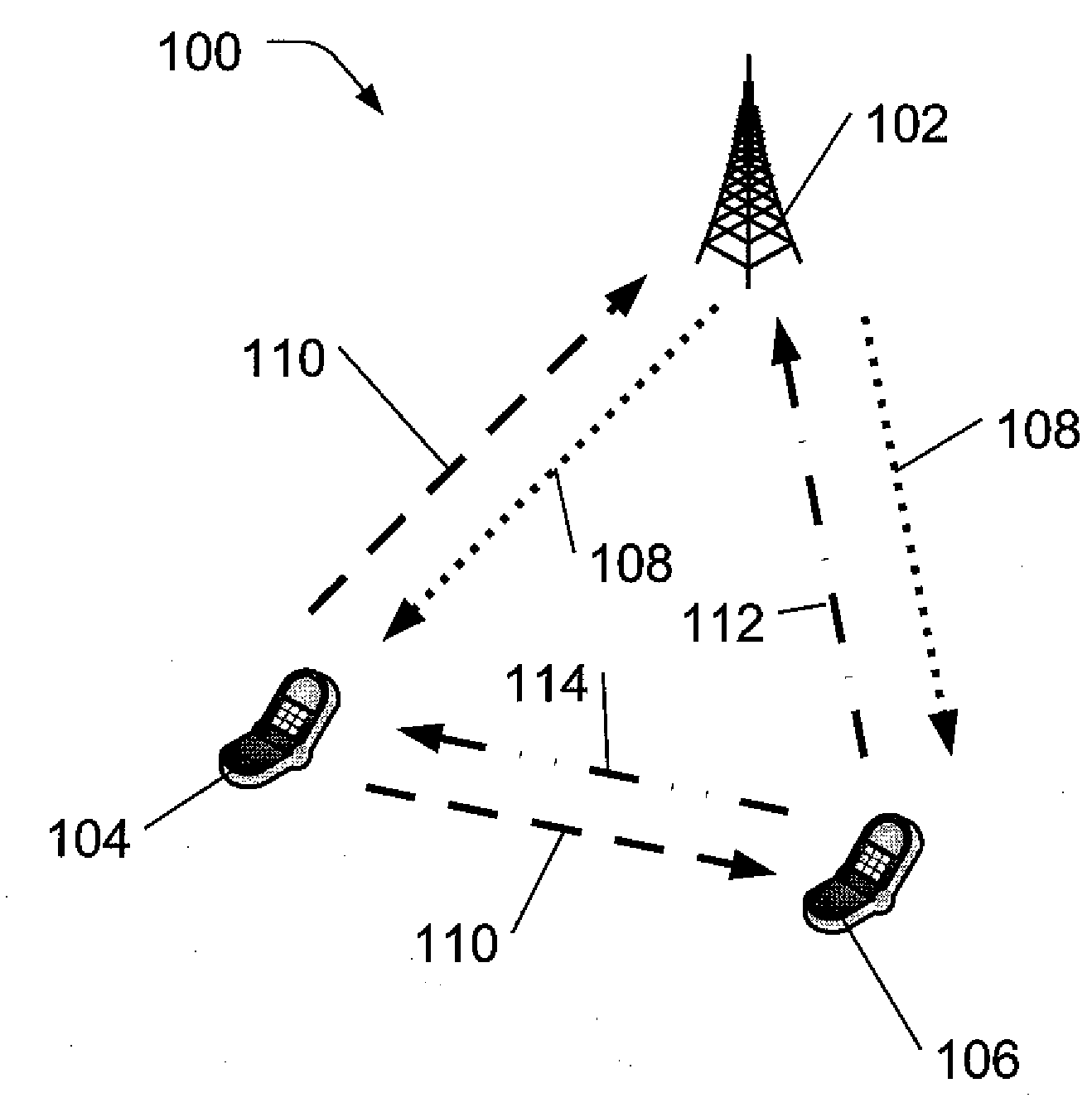
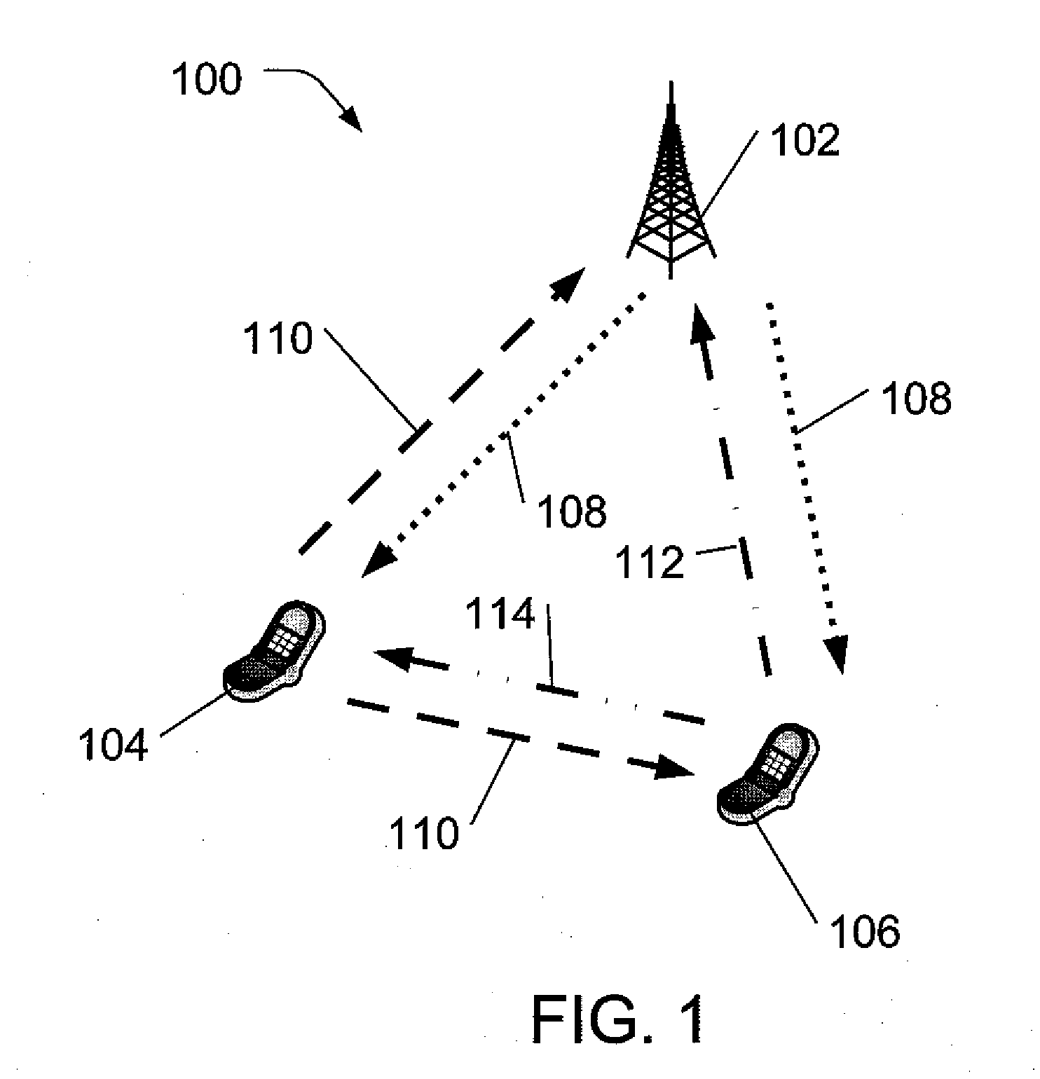
[0011]Embodiments further provide an autonomous relay station for communicating data between a mobile communication device and a core network, the autonomous relay station comprising a processor, a radio module, a control module, a motion driver, and a memory, the memory comprising a set of instructions that when executed by the processor causes the autonomous relay station device to relay network encoded data.

Problems solved by technology

As the distance increases between user equipment and base stations increases, the transmission power required for error-free communication also increases, until maximum transmission power is reached and no further increase is possible.
While increasing the transmission power may increase the range of communication, it may also contribute to interference, reducing the signal quality within the coverage area of a base station or cell, as well as in adjacent coverage areas or cells.
Similar problems may arise as an increasing number of user equipment devices communicate with a base station having limited communication resources.
In case of a high traffic load within the coverage area of a single base station or cell, the quality of service may be reduced for users, due to inefficient utilization of available resources, or due to the limits of the available communication resources.
Unfortunately, new base stations have a number of drawbacks, including the difficulty of selecting suitable locations, establishment of high bandwidth ongoing connections to a core network and the continuous operating costs of maintaining such connections, and (in some cases) resistance encountered from the residents of the area in which the new base station will be established.
Overall, the costs and difficulties of adding new base stations to a wireless communication system may make this an undesirable solution.
One difficulty with these approaches, however, is that they are generally based on the assumption that the user equipment as well as the base station and relay stations are mostly static.
Unfortunately, this assumption does not apply in many cases.

Method used


Image

  • System and method for optimizing network wireless communication resources
  • System and method for optimizing network wireless communication resources
  • System and method for optimizing network wireless communication resources

Examples


Embodiment Construction

[0023]In the past, relay stations in multi-hop networks typically had fixed locations and relatively constant coverage areas. However, dynamic relay stations may soon be added to many mobile communication networks. Generally, dynamic relay stations are stations that may change their relay coverage area and / or signal dynamically, including, for example, changing their location, reconfiguring their antennae, or adjusting output power. Although such dynamic relay stations offer the promise of being able to dynamically reconfigure a wireless communication network to improve and adapt network performance to changing needs, they may also lead to added complexity, since user equipment and base stations will no longer be able to rely on a relatively stable wireless network configuration and indeed may be dynamic relay stations themselves. In various embodiments, dynamic relay stations may dynamically change, for example, because of base station initiated commands, other dynamic relay initia...


PUM


Abstract

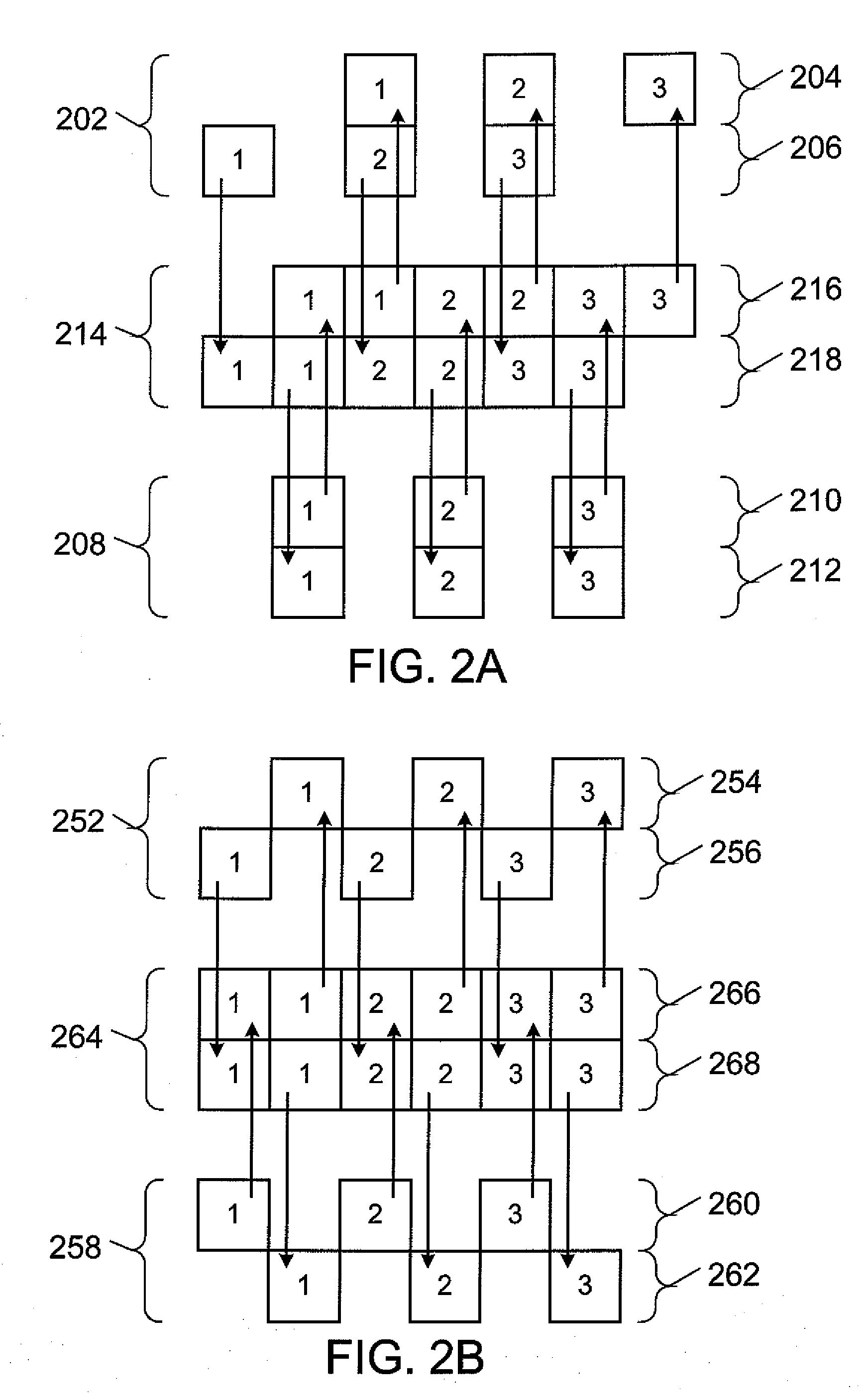
Embodiments are described that provide methods and radio networks that communicate data between a mobile communication device and a core network. The methods include using network coding to encode data, and communicating a subset of the encoded data between the mobile communication device and the core network through a dynamic relay station.

Description

BACKGROUND OF THE INVENTION[0001]Mobile wireless communication systems currently include base stations, having fixed locations and connections to a core network, and mobile communication devices (also referred to as a “User Equipment” or UE, and / or as “terminals”) that move within the areas covered by the central base stations, and may also move out of the range of central base stations. As the distance increases between user equipment and base stations increases, the transmission power required for error-free communication also increases, until maximum transmission power is reached and no further increase is possible. Beyond this distance, no communication link may be established, and the user equipment is out of range of the base station, and may need to switch to communication through another base station or cell, if one is available. While increasing the transmission power may increase the range of communication, it may also contribute to interference, reducing the signal qualit...

Claims


Application Information

Patent Timeline
Patent Type & Authority Applications(United States)
IPC IPC(8): H04L12/66H04B7/14
CPCH04B7/15521H04B7/2606H04L1/0017H04L1/004H04L2001/0097H04W24/02H04W28/00H04W88/04H04B7/14H04W16/26H04W16/20
Inventor DREWES, CHRISTIANMUECK, MARKUSLE, THUYENCHOI, HYUNG-NAM
Owner INTEL CORP
Learn More