Vibration sensor assembly with ambient noise detection

a technology of vibration sensor and ambient noise, which is applied in the field of vibration sensor assembly for detecting vibrational energy, can solve the problems of affecting the safety of the detector, the surface on which the detector is mounted, and the inability of the movement sensor to be used to alarm the building

Inactive Publication Date: 2010-07-22
WAIKATOLINK LIMITED
View PDF5 Cites 10 Cited by
  • Summary
  • Abstract
  • Description
  • Claims
  • Application Information

AI Technical Summary

Benefits of technology

[0050]Preferably the sensor assembly of the present invention may include at least one processing element. This processing element may preferably be a microprocessor, configured to receive signals from the transducers and to compare same. Having the processing carried out by a processor in the sensor assembly may provide the advantage of a self-contained, tamper-proof unit.
[0051]In some other embodiments the output from the transducers may be processed separately from the sensor assembly, for example by a remote processor. The connection to the remote processor may be done wirelessly in order to avoid tampering with a physical connection (such as wires) between the sensor assembly and the processor.

Problems solved by technology

However, such movement sensors are not suitable for buildings containing something which moves inside the building, such as a household pet or other animal.
Movement sensors are also not suitable for alarming the building when someone is inside the building.
A loud noise can indicate that the surface on which the detector is mounted has probably been tampered with.
Systems that use acoustic threshold detector technology with signal processing capability generally require considerable signal processing power to process the complex signals and then to determine whether a specific noise crosses an alarm trigger threshold.
A deficiency with these detectors is that loud ambient noises that are not related to tampering can set off alarms.
False alarms are highly undesirable, causing inconvenience to the building users, owners and surrounding sites.
However, this type of detector is quite complicated, and high frequency noises in the same band which are not the result of broken glass may still trigger the alarm.
These detectors also cannot be arranged to detect other sounds, such as doors being forced open.

Method used


Image

  • Vibration sensor assembly with ambient noise detection
  • Vibration sensor assembly with ambient noise detection
  • Vibration sensor assembly with ambient noise detection

Examples


Embodiment Construction

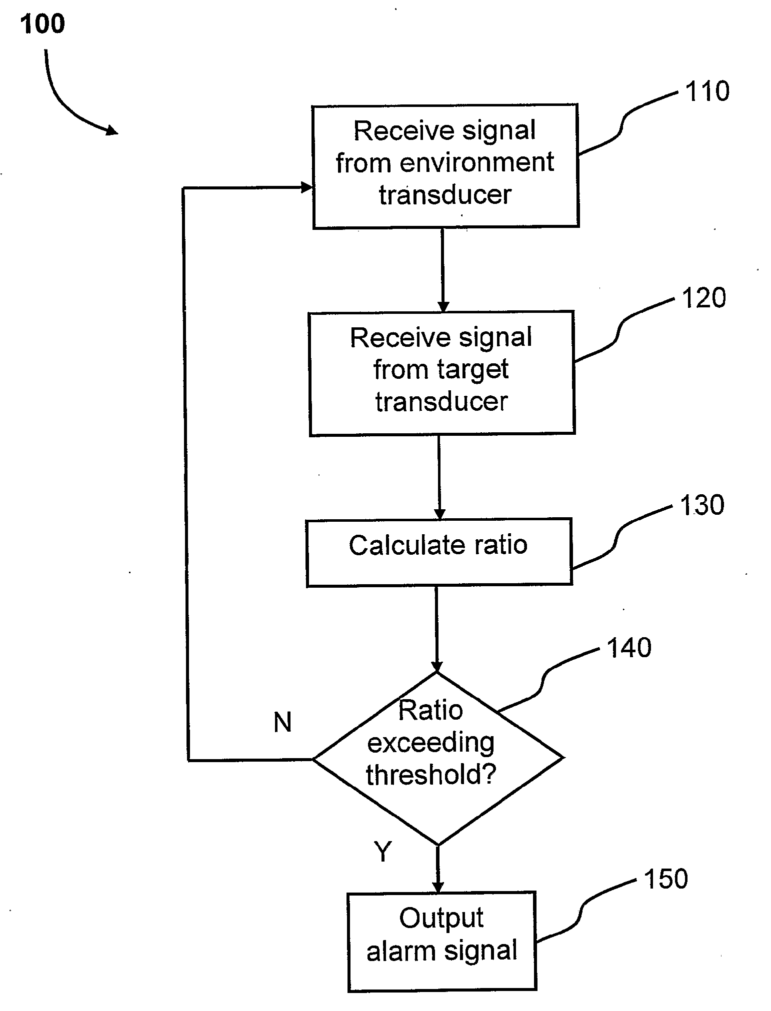
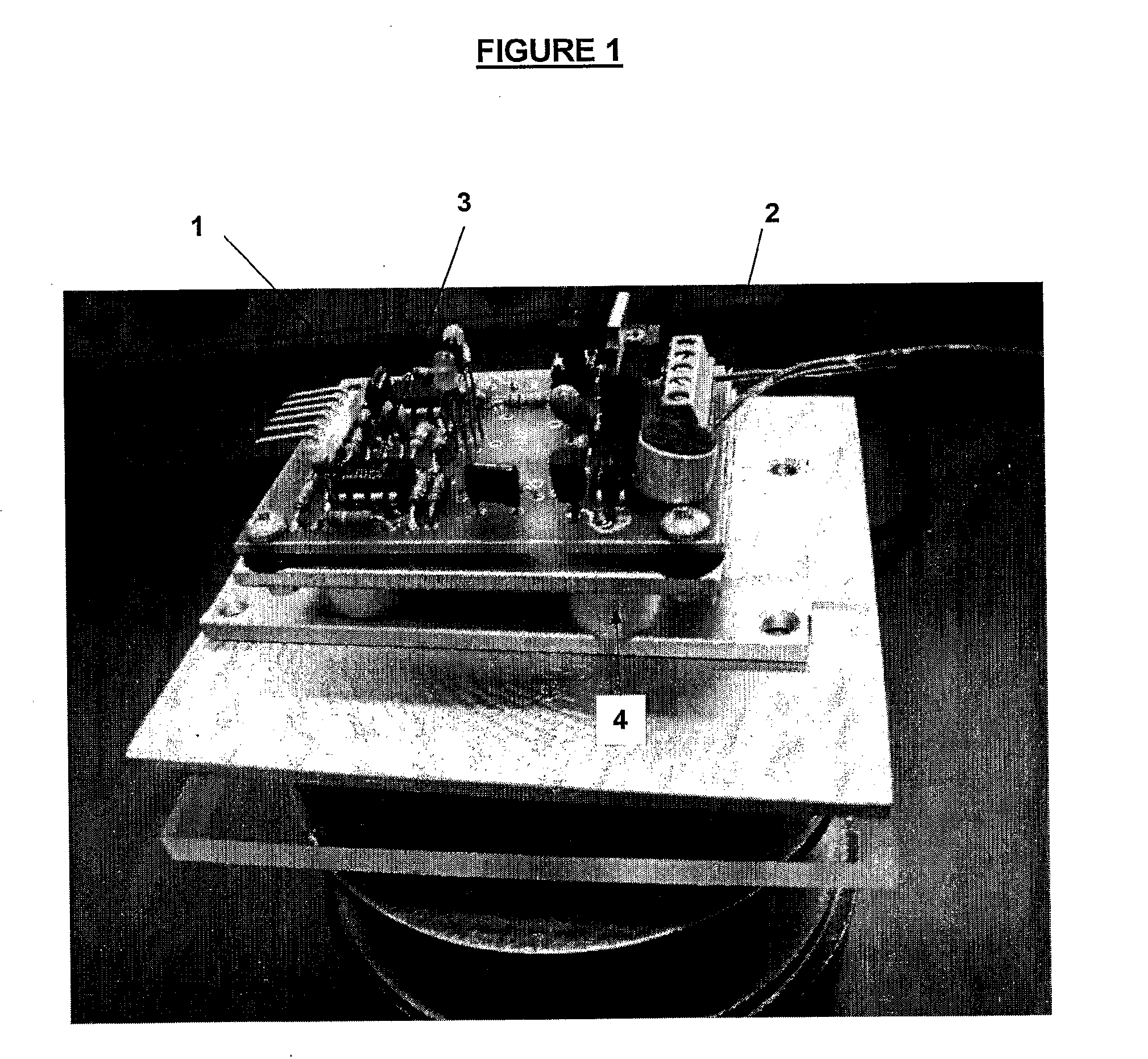
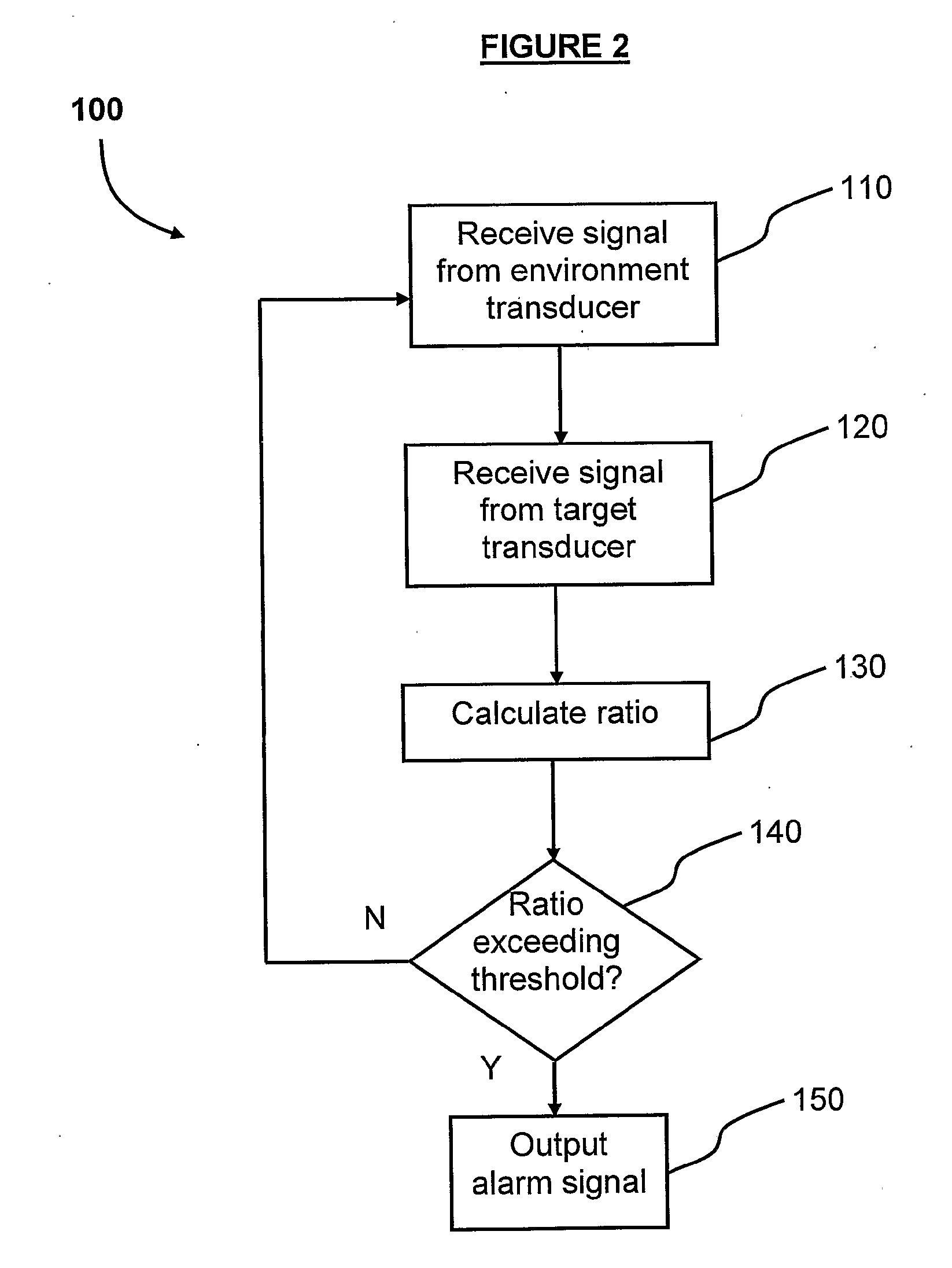
[0062]FIG. 1 shows a sensor assembly 1 according to a preferred embodiment. The sensor assembly 1 includes a target vibration transducer 3, in the form of an audio transducer, and an environmental vibration transducer 2, also in the form of an audio transducer.

[0063]The target vibration transducer 3 is attached to a first mount, in the form of a base plate 7, that is configured to acoustically couple to a target surface (not shown).

[0064]The target vibration transducer 3 is attached to the base plate 7 and configured to detect audio energy in the base plate 7. In this way when the base plate 7 is acoustically coupled to a target surface the target vibration transducer 3 detects audio energy transferred from the target surface to the base plate 7.

[0065]The target surface may be an exterior surface of a building, such as a window, window frame, door, or roof of a building, or a fence such as a security fence. This allows the sensor to detect disturbances on that surface. In practice t...


PUM


Abstract

A sensor assembly for detecting vibrational energy on a target surface, including at least one target vibration transducer configured to measure vibrational energy associated with at least one target surface; and at least one environmental vibration transducer, each environmental vibration transducer being configured to measure vibrational energy in the immediate vicinity of the environmental vibration transducer wherein the environmental vibration transducer is vibrationally isolated from the target vibration transducer.

Description

TECHNICAL FIELD[0001]The present invention relates generally to sensors, and in particular to a sensor assembly for detecting vibrational energy on a surface.BACKGROUND ART[0002]There are many types of sensors which may be configured to detect unauthorised entry or tampering with a building or vehicle. Typically these sensors are attached to some type of alarm which may sound on detection of an intruder.[0003]For example, sensors may be placed inside a building and set when there is expected to be no movement within the building. However, such movement sensors are not suitable for buildings containing something which moves inside the building, such as a household pet or other animal. Movement sensors are also not suitable for alarming the building when someone is inside the building.[0004]To overcome the deficiencies of movement sensors, there are a number of “tamper detectors” available. These detectors detect loud noises, for example such as made by a glass window breaking, which ...

Claims


Application Information

Patent Timeline
Patent Type & Authority Applications(United States)
IPC IPC(8): H04R29/00
CPCG01H3/00G08B13/1672
Inventor COSGROVE, MICHAEL CHARLESROSBOROUGH, DANIEL BRETTSCOTT, JONATHAN BRERETON
Owner WAIKATOLINK LIMITED
Why Eureka
Try Eureka