Optical fiber mechanical wedge splice

Active Publication Date: 2010-07-22
LIN PARRY
View PDF9 Cites 11 Cited by
  • Summary
  • Abstract
  • Description
  • Claims
  • Application Information

AI Technical Summary

Benefits of technology

[0021]By way of the above-mentioned illustration of the concept, it can be known that the wedge type mechanical optical fiber splice can align and fasten the two optical fibers tightly in the V-grooved block by using the first wedge to press the pushing block towar

Problems solved by technology

Therefore, it exists the drawback of insufficient stability.
Since only the optical fiber 34, rather than the jacket 34, is fastened, the stability of such a structure might still be insufficient.
Since the structure disclosed in U.S. Pat. No. 5,638,477 is complicated and the jacket rather than the optical fiber is directly fastened, it also has the drawback of insufficient stability.
Therefore, stability also might be insufficient.
Since the naked optical fibers 64 and

Method used


Image

  • Optical fiber mechanical wedge splice
  • Optical fiber mechanical wedge splice
  • Optical fiber mechanical wedge splice

Examples


Embodiment Construction

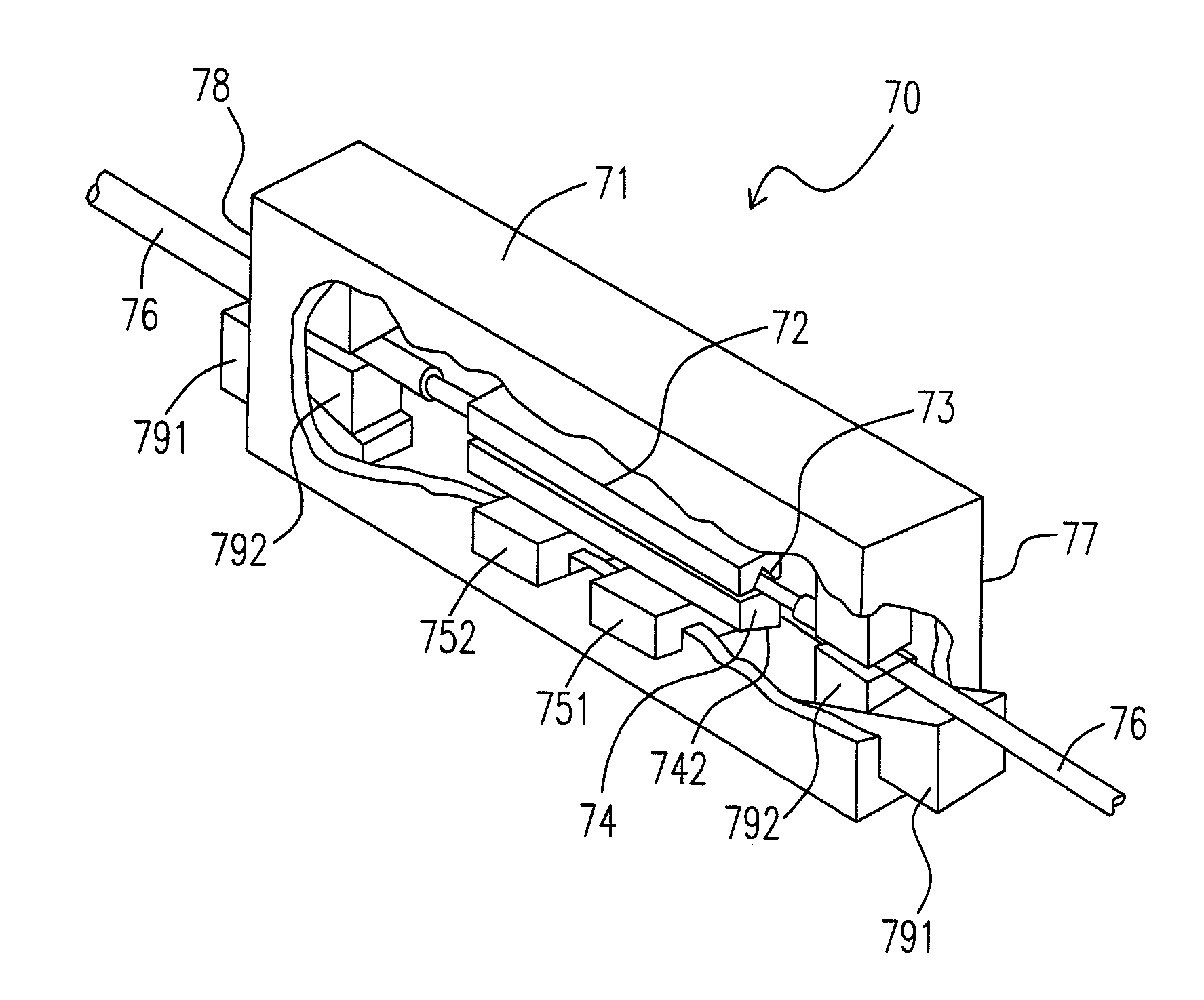
[0033]Please refer to FIG. 7, which illustrates an wedge-type mechanical optical fiber splice 70, which includes a housing 71 which is a hollow block 71 having two openings for guiding optical fibers 76 at two opposite ends 77, 78; a V-grooved block 72 which is a first long strip block and one surface of the long strip block has a V groove 73; a pushing block 74, which is a second long strip block and preferably has a beveled surface or a slope 742, confronting to the V groove 73; and a first wedge 751 which is a block having an oblique angle. (A oblique angle is either a blunt angle or an acute angle, as defined in the field of Mathematics.) In other words, the first wedge 751 has a beveled surface or a slope (not shown) which is neither parallel nor perpendicular to the other surfaces of the first wedge 751, and the slope of the first wedge 751 fits with that of the pushing block 74.) Taking advantage of the mechanism of wedge, one may use the first wedge 751 to push the pushing b...


PUM


Abstract

A wedge-type mechanical optical fiber splice is provided in the present invention. The splice comprises a housing, a V-grooved block, a pushing block, and a first wedge. The housing is a hollow block, and has two openings for guiding optical fiber at two opposite sides. The V-grooved block, so called a first block, is a long strip block having a V-shaped groove on its surface. The pushing block, so called a second block, confronts to the V-grooved block. The first wedge is a wedged-type block. The second block is moved toward the first block or the first block is moved toward the second block by pushing down the first wedge, so that two optical fibers are aligned and secured in the V groove.

Description

FIELD OF THE INVENTION[0001]The present invention relates to a wedge type mechanical splice. In particular, the present invention relates to an optical fiber splice which aligns and fastens two optical fibers in a V-grooved block by the wedge, so as to achieve the effects such as high tensile strength and easy alignment, etc.BACKGROUND OF THE INVENTION[0002]The regular mechanical optical fiber splice is used in the connection of two optical fibers to maintain optical signal transmission. The mechanical optical fiber splice includes two parts, the fiber fastening section and the jacket (or named as “buffer”) fastening section. Please refer to FIG. 1, which is the diagram in U.S. Pat. No. 4,730,892 entitled “OPTICAL FIBER MECHANICAL SPLICE”. In FIG. 1, a splice device 10 is shown, in which an adjustment screw 11 is configured to fasten the fiber fastening section 12, and two stud clamps 13, 14 to fasten the jacket fastening sections (i.e. V-grooves) 15, 16, respectively. Since a screw...

Claims


Application Information

Patent Timeline
IPC IPC(8): G02B6/38G02B6/255
CPCG02B6/3801
Inventor LIN, PARRY
Owner LIN PARRY
Why Eureka
Try Eureka