User interface device for controlling a consumer load and light system using such user interface device

a user interface device and user interface technology, applied in static indicating devices, lighting and heating apparatuses, instruments, etc., can solve the problems of large space requirements for the overall light controller, difficult use of the user interface device by average users, and complex control of such advanced light appliances. achieve the effect of convenient operation

Inactive Publication Date: 2011-04-14
KONINKLIJKE PHILIPS ELECTRONICS NV
View PDF10 Cites 3 Cited by
  • Summary
  • Abstract
  • Description
  • Claims
  • Application Information

AI Technical Summary

Benefits of technology

[0009]Thus, it is an object of the present invention to provide a user interface device for controlling an electrical consumer

Problems solved by technology

Since these advanced light appliances include a plurality of different lamps and in particular multiple full color light sources and/or variable color temperature light sources, the control of such advanced light appliance is very complex.
This results not only in a huge space requirement for the overall light controller but makes the user interface device also difficult to use for average users.
However, the application of conventional control devices for controlling an electrical consumer load is getting more complex or unmanageable with an increase of the complexity of the overall system.
This makes it difficult to use conventional contr

Method used


Image

  • User interface device for controlling a consumer load and light system using such user interface device
  • User interface device for controlling a consumer load and light system using such user interface device
  • User interface device for controlling a consumer load and light system using such user interface device

Examples


Embodiment Construction

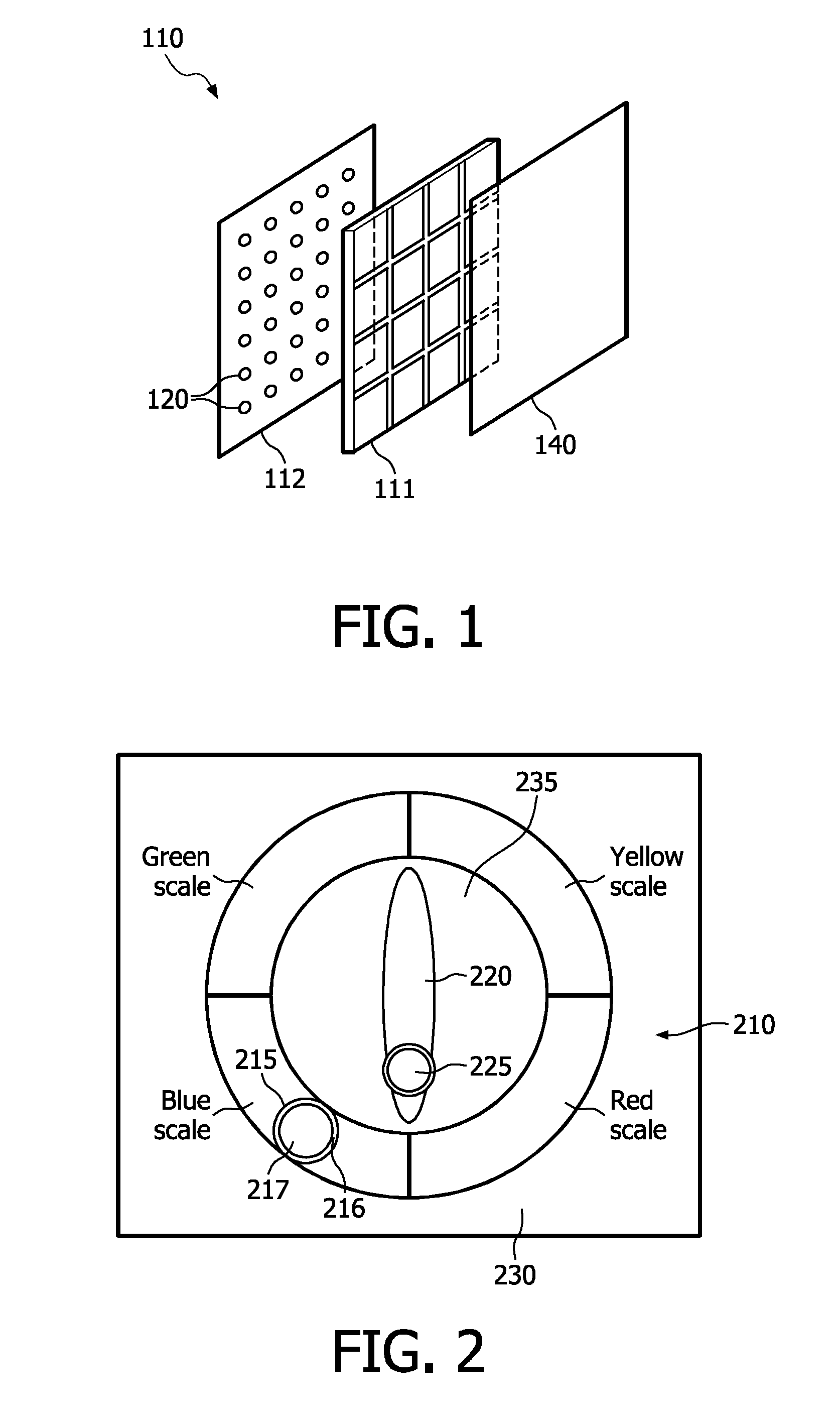
[0047]In FIG. 1 the mechanical construction of the inventive user interface device is illustrated having three layers. The first layer includes the display layer 112 having a plurality of LEDs 120 arranged in matrix form. In front of the display device 112, there is an input unit 111, which may be realized as a touch pad having areas for detecting positions of user input. Moreover, a cover layer 140 may be arranged in front of the input unit 111 to protect the underlying first and second layers. The cover layer 140 may have a diffusing function to diffuse the light outputted by the LED matrix.

[0048]FIG. 2 illustrates a schematic layout, which could be displayed by the LED matrix 120 on the display device 112. There may be a first colored scale 210 illustrating a color scale starting from the yellow scale in the first quadrant and a green scale in the second quadrant followed by a blue scale in a third quadrant and a red scale in the fourth quadrant. Within the four scales, the color...


PUM


Abstract

The invention relates to a user interface device for controlling an electrical consumer, in particular, a light system (545). Further, it relates to light system using such user interface device. To provide a user interface device for controlling a light system (545), which could be easily operated and provides the possibility to recognize a selected preset in all areas of the display device (112), a user interface device for controlling a consumer load (545) is proposed, comprising: an input device (111); and a display device (112), wherein the input device (111) and the display device (112) are arranged interested to each other in one common layer or in two layers respectively stacked on each other. The display device (112) is adapted to display at least a first colored scale (210) indicating a first range of values adjustable by an user input on the first colored scale (210) and to display a first feedback indicator (215) within the first colored scale (210) indicating the current value of the first range of values output by the user interface device to a consumer load (545).

Description

FIELD OF THE INVENTION[0001]The invention relates to a user interface device for controlling an electrical consumer, in particular, a light system. Further, it relates to light system using such user interface device.BACKGROUND OF THE INVENTION[0002]In the fields of electrical power control user interface devices like switches or dimmers are used to adjust an amount of an electrical power provided from an electrical power source to an electrical consumer load. The electrical consumer load might be a lamp in a lighting system including a plurality of different lamps, an electrical motor in a home appliance like a kneading machine or in a vacuum cleaner or an electrical heater. In the easiest case the switch is a hard switch for merely switching on / off the power supply to the electrical consumer load. In an on state, the maximum available electrical power is supplied to the electrical consumer load and in the off-state, no electrical power is supplied to the electrical consumer load. ...

Claims


Application Information

Patent Timeline
IPC IPC(8): G09G5/00F21V9/00H05B44/00
CPCH05B33/0863H05B45/20H05B47/10H05B47/165G06F3/0412G06F3/0416G06F2203/04103H05B45/22
Inventor DIEDERIKS, ELMO MARCUS ATTILA
Owner KONINKLIJKE PHILIPS ELECTRONICS NV
Why Eureka
Try Eureka