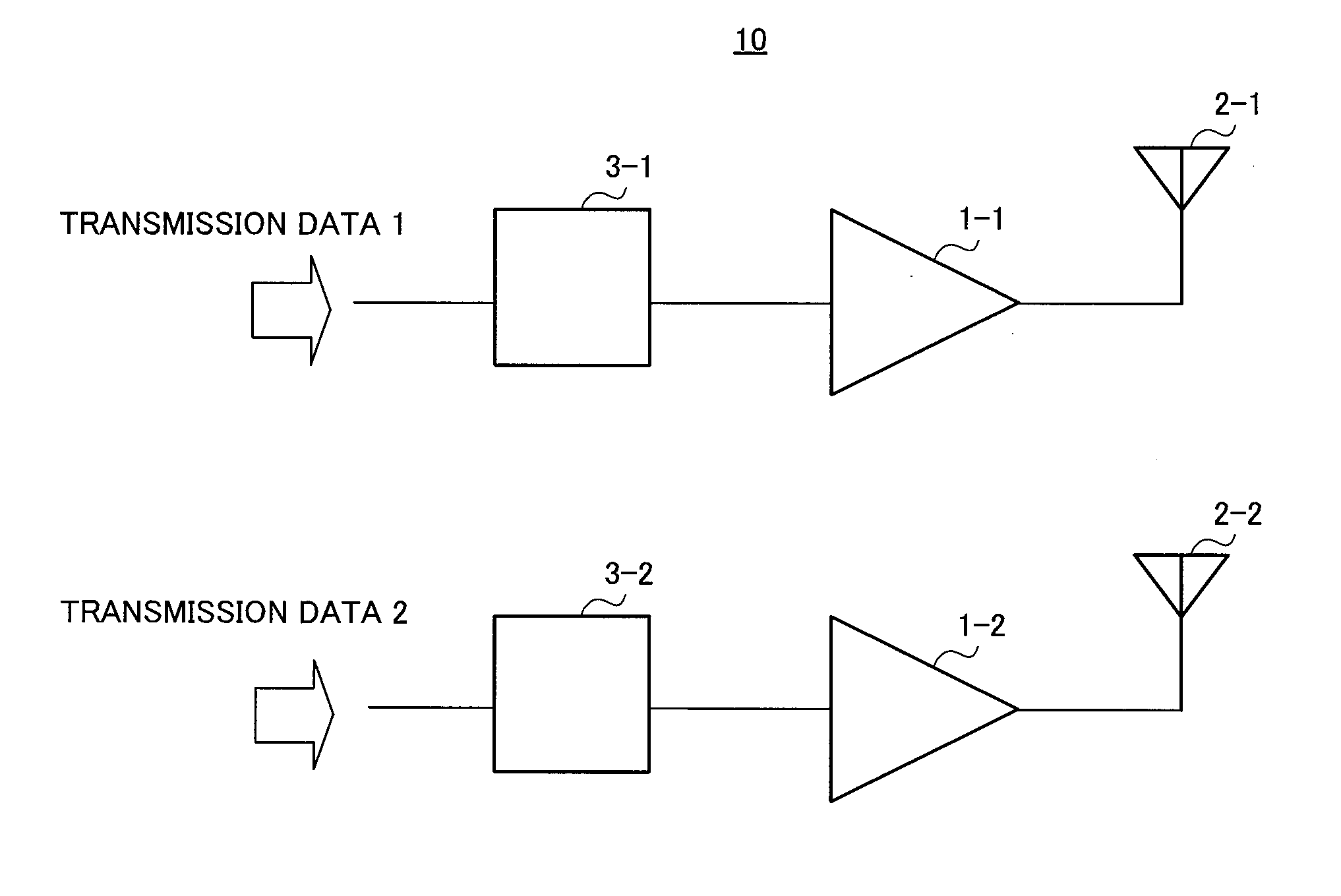
MIMO transmitter

a technology of transmitting apparatus and microphone, which is applied in the direction of transmission monitoring, high-level techniques, and baseband system details, etc., can solve the problems of reducing the efficiency of the amplifier, the large-sized base station apparatus, and the short duration of the heat radiation of the mobile terminal's battery according to an increase in the power consumption of the power amplifier, so as to achieve high-efficiency power amplification

Inactive Publication Date: 2010-07-22
PANASONIC CORP
View PDF3 Cites 5 Cited by
  • Summary
  • Abstract
  • Description
  • Claims
  • Application Information

AI Technical Summary

Benefits of technology

[0014]According to the present invention, it is possible to provide a MIMO transmitting apparatus that allows high-efficiency power amplification even in a signal with a wide dynamic range or high PAPR.

Problems solved by technology

As mobile and stationary radio communication is promoted to broadbandaization in the future, a large-sized base station apparatus, or short duration and heat radiation of a mobile terminal's battery according to an increase in power consumption of a power amplifier become a big problem.
Generally, when PAPR is high, it is necessary to increase the back-off of an amplifier, and therefore the efficiency of an amplifier decreases.

Method used


Image

  • MIMO transmitter
  • MIMO transmitter
  • MIMO transmitter

Examples


embodiment 1

[0022]As shown in FIG. 3, MIMO transmitting apparatus 100 has radio signal generation sections 110 and 120, peak detection section 130, branch switching section 140, amplifiers 150 and 160, and antennas 170 and 180.

[0023]Radio signal generation section 110 receives transmission data sequence 1 as input, and performs modulation processing and radio processing (e.g. up-conversion) on transmission data sequence 1, to generate the first transmission sequence in a radio frequency.

[0024]Radio signal generation section 120 receives transmission data sequence 2 as input, and performs modulation processing and radio processing (e.g. up-conversion) on transmission data sequence 2, to generate a second transmission sequence in a radio frequency.

[0025]Peak detection section 130 detects the envelope of the first transmission sequence outputted from radio signal generation section 110. Further, peak detection section 130 detects peak values (maximum values) of the detected envelope. Peak detectio...

embodiment 2

[0054]As shown in FIG. 4, MIMO transmitting apparatus 200 has variable amplifier 210 provided on the input side of amplifier 150 and variable amplifier 220 provided on the input side of amplifier 160.

[0055]Variable amplifier 210 receives the comparison result from peak detection section 130 and switches the gain according to this comparison result.

[0056]To be more specific, variable amplifier 210 sets greater gain when the comparison result shows that the peak value is greater than the threshold value, than the gain when the comparison result shows that the peak value is equal to or less than the threshold value.

[0057]Variable amplifier 220 receives the comparison result from peak detection section 130 and switches the gain according to this comparison result. To be more specific, variable amplifier 220 sets greater gain when the comparison result shows that the peak value is greater than the threshold value, than the gain when the comparison result shows that the peak value is equa...

embodiment 3

[0061]As shown in FIG. 5, MIMO transmitting apparatus 300 according to the present embodiment has branch switching section 310. This branch switching section 310 has delay addition section 312.

[0062]Delay addition section 312 is arranged between division section 144 and combination section 146. Delay addition section 312 gives a delay to part of the first transmission sequence divided in division section 144.

[0063]By adopting this configuration, the first transmission sequence transmitted via antenna 170 and the first transmission sequence transmitted via antenna 180 are transmitted with a relative phase difference. By this means, it is possible to reduce to lower received level of the first transmission sequence on the receiving side, due to mutual interfering between the first transmission sequence transmitted via antenna 170 and the first transmission sequence transmitted via antenna 180 on the channel path.

[0064]Duration of delay with which the first transmission sequence transm...


PUM


Abstract

A MIMO transmitter capable of highly efficient power amplification over a wide dynamic range or for a high PAPR signal. In the MIMO transmitter (100), an amplifier (150) amplifies an input signal and outputs the amplified signal to an antenna (170). An amplifier (160) amplifies an input signal and outputs the amplified signal to an antenna (180). A peak detection part (130) detects an envelope of a first transmission sequence. A branch switching part (140) switches over to input all of the first transmission sequence to the amplifier (150) or to input part of the first transmission sequence together with a second transmission sequence to the amplifier (160) based on comparison results between the envelope detection result of the first transmission sequence and a threshold value. This constitution can reduce a peak of the input signal of the amplifier, and thus the amplifier can be efficiently used. As a result, the MIMO transmitter capable of highly efficient power amplification for a high PAPR signal and the like can be realized.

Description

TECHNICAL FIELD[0001]The present invention relates to a MIMO transmitting apparatus adopting Multiple Input Multiple Output (MIMO) technique of receiving by a plurality of antennas a radio signal transmitted from a plurality of antennas and carrying out radio communication.BACKGROUND ART[0002]As mobile and stationary radio communication is promoted to broadbandaization in the future, a large-sized base station apparatus, or short duration and heat radiation of a mobile terminal's battery according to an increase in power consumption of a power amplifier become a big problem. For this reason, a power amplifier is required to be capable of amplifying a high speed signal having a wide bandwidth with low distortion and high efficiency.[0003]Methods of realizing high-efficiency modulation and amplification include a Doherty amplification scheme, an ET (Envelope tracking) scheme, an EER (Envelope Elimination Restoration) scheme and so on.[0004]Meanwhile, to increase the transmission capac...

Claims


Application Information

Patent Timeline
Patent Type & Authority Applications(United States)
IPC IPC(8): H04B1/04
CPCH04B1/0483H04B7/0426Y02D70/444H04L27/2614Y02D70/40H04B7/0689Y02D30/70
Inventor TOUGOU, HITOMARO
Owner PANASONIC CORP
Why Eureka
Try Eureka