Power amplifier circuit

Active Publication Date: 2020-05-07
MURATA MFG CO LTD
View PDF0 Cites 0 Cited by
  • Summary
  • Abstract
  • Description
  • Claims
  • Application Information

AI Technical Summary

Benefits of technology

The present disclosure provides a power amplifier circuit that uses multiple amplifiers to achieve high-efficiency power amplification.

Problems solved by technology

Japanese Unexamined Patent Application Publication No. 2006-5643 assumes a single transistor stage, and no sufficient studies are made on a method for high-efficiency power amplification with a configuration in which a plurality of transistors are connected in series.

Method used


Image

  • Power amplifier circuit
  • Power amplifier circuit
  • Power amplifier circuit

Examples


first embodiment

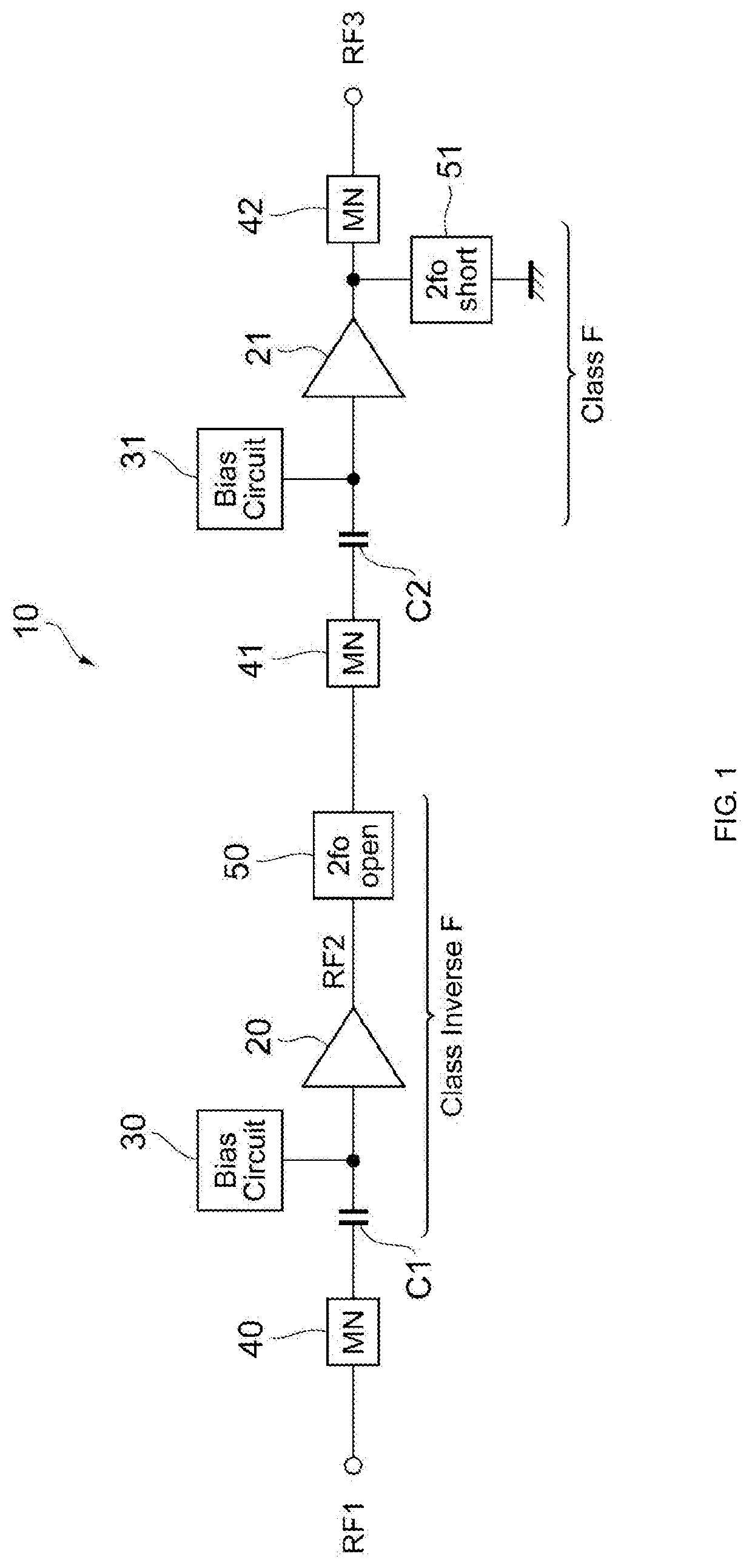
[0024]FIG. 1 illustrates an example configuration of a power amplifier circuit 10 according to the present disclosure. The power amplifier circuit 10 is mounted in, for example, a mobile communication device such as a mobile phone and is used to amplify the power of a radio-frequency (RF) signal to be transmitted to a base station. For example, the power amplifier circuit 10 amplifies transmission signals conforming to communication standards such as the second-generation mobile communication system (2G), the third-generation mobile communication system (3G), the fourth-generation mobile communication system (4G), the fifth-generation mobile communication system (5G), Long Term Evolution Frequency Division Duplex (LTE-FDD), LTE Time Division Duplex (LTE-TDD), LTE-Advanced, and LTE-Advanced Pro. The RF signal has a frequency of about several hundreds of megahertz (MHz) to about several tens of gigahertz (GHz), for example. The power amplifier circuit 10 may amplify signals having oth...

second embodiment

[0063]FIG. 10 illustrates the circuit configuration of a power amplifier circuit 10D according to the present disclosure.

[0064]As illustrated in FIG. 10, in the power amplifier circuit 10D, the configuration of the subsequent amplifier 21 is different from that in the embodiment described above. Specifically, unlike the power amplifier circuit 10A, the power amplifier circuit 10D includes a transistor Q3, a bias circuit 32, an adjustment circuit 60, a capacitor C9, and inductors L6 and L7. In FIG. 10, capacitors corresponding to the capacitors C3 and C4 illustrated in FIG. 3 are not illustrated.

[0065]As in the embodiment described above, the transistor Q2 (lower transistor) has a collector (first terminal) to which the power supply voltage Vcc (second power supply voltage) is supplied via the inductor L2, an emitter (second terminal) connected to ground, and a base (third terminal) to which the RF signal RF2 (second signal) is supplied via the capacitor C2.

[0066]The transistor Q3 (u...


PUM


Abstract

A power amplifier circuit includes a first amplifier that amplifies a first signal, and a second amplifier arranged subsequent to the first amplifier. The second amplifier amplifies a second signal that is based on an output signal of the first amplifier. The first amplifier performs class inverse-F operation, and the second amplifier performs class F operation.

Description

[0001]This application claims priority from Japanese Patent Application No. 2018-207343 filed on Nov. 2, 2018. The content of this application is incorporated herein by reference in its entirety.BACKGROUND[0002]The present disclosure relates to a power amplifier circuit. In power amplifier circuits mounted in mobile communication devices such as mobile phones, it is desirable to increase the power of transmission signals with high efficiency. A known method to realize such high-efficiency power amplification is so-called class F operation. In the class F operation, reducing the temporal overlap between voltage and current waveforms at a transistor that performs power amplification reduces power consumption. For example, Japanese Unexamined Patent Application Publication No. 2006-5643 discloses a radio-frequency amplifier circuit in which an LC parallel resonator disposed at least one of between a collector of a transistor and an output terminal and between an emitter of the transist...

Claims


Application Information

Patent Timeline
IPC IPC(8): H03F1/02H03F1/56
CPCH03F2200/387H03F2200/451H03F1/0205H03F2200/516H03F2200/411H03F1/565H03F3/217H03F3/60H03F3/211H03F1/0211H03F3/195H03F2200/391
Inventor NAMIE, HISANORISAMATA, MITSUNORITANAKA, SATOSHI
Owner MURATA MFG CO LTD
Why Eureka
Try Eureka