High-efficiency linear power amplifier

Active Publication Date: 2006-05-09
NTT DOCOMO INC
View PDF11 Cites 96 Cited by
  • Summary
  • Abstract
  • Description
  • Claims
  • Application Information

AI Technical Summary

Benefits of technology

[0009]It is therefore an object of the present invention to provide a high-efficiency linear power

Problems solved by technology

On this account, an amplifier design by the output backoff scheme encounters difficulty in achieving predetermined linear amplification in the region of transmitting output power in which to perform high-efficiency amplificati

Method used


Image

  • High-efficiency linear power amplifier
  • High-efficiency linear power amplifier
  • High-efficiency linear power amplifier

Examples


Embodiment Construction

High-Efficiency Linear Power Amplifier

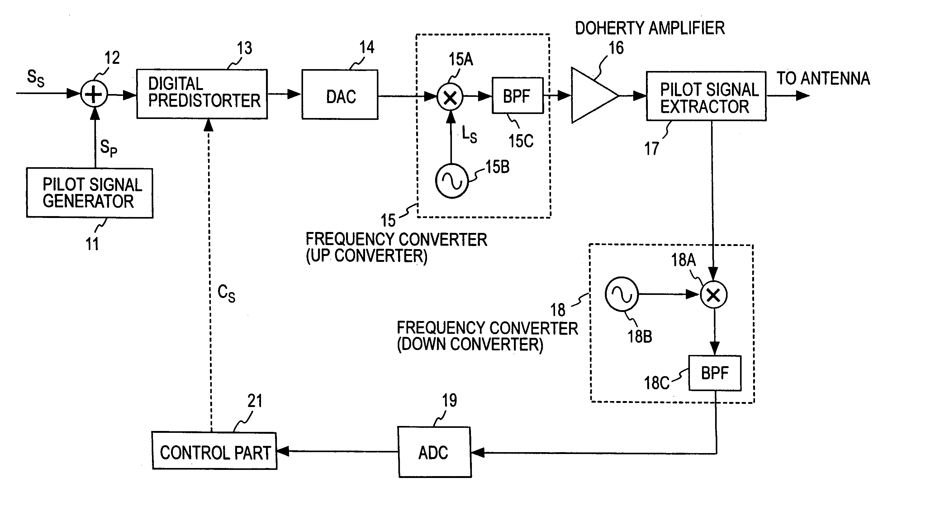
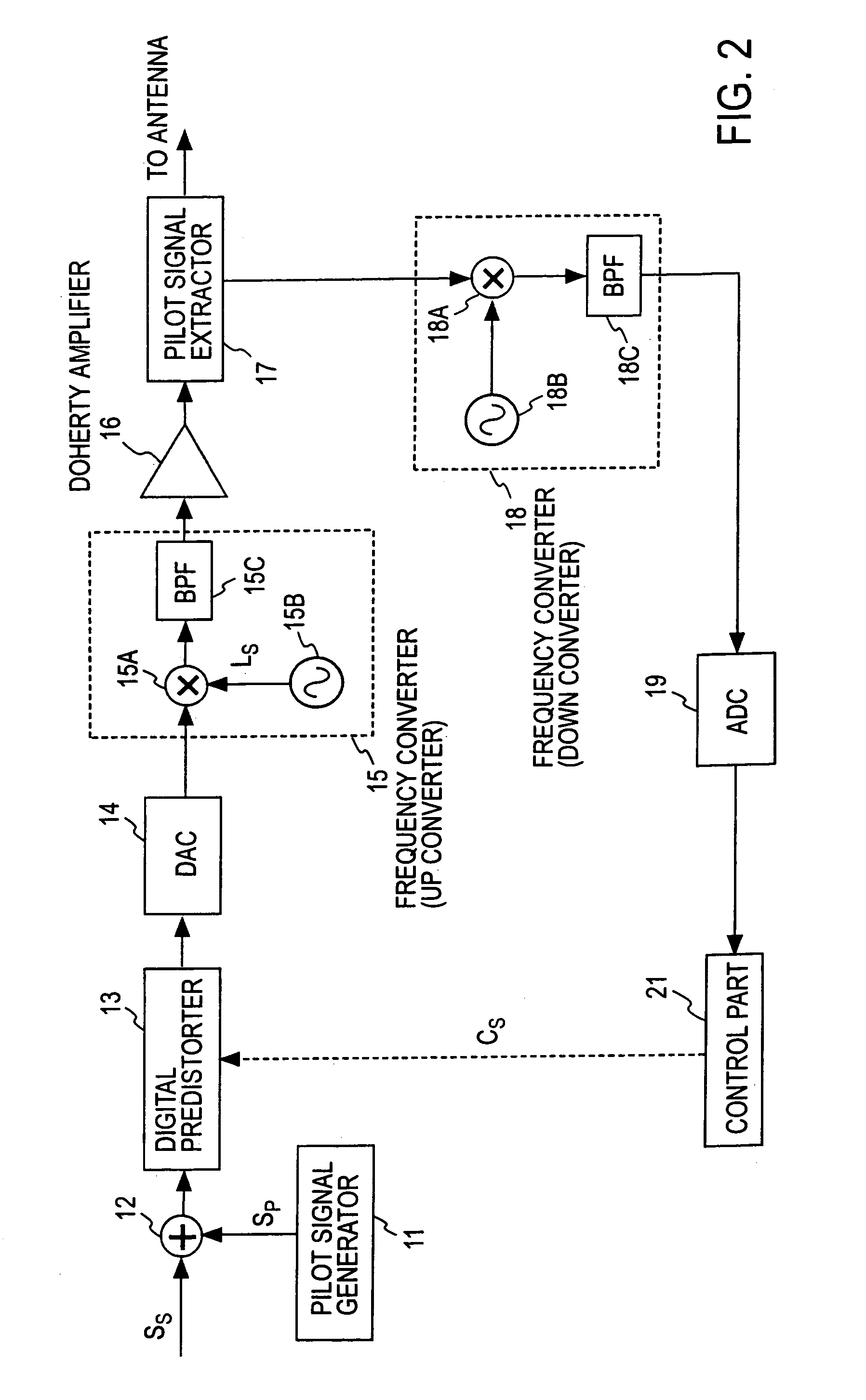
[0026]FIG. 2 illustrates an embodiment of the high-efficiency linear amplifier according to the present invention.

[0027]The high-efficiency linear power amplifier according to this embodiment comprises: a pilot signal generator 11, an adder 12 for adding a transmission signal SS and a pilot signal SP; a digital predistorter 13; a digital-analog converter (DAC) 14 for converting a predistorted signal to an analog signal; a frequency converter (up converter) composed of a mixer 15A, a local oscillator 15B and a band-pass filter (BPF) 15C; a Doherty amplifier 16; a pilot signal extractor 17 for extracting the pilot signal; a frequency converter (down converter ) 18 composed of a mixer 18A, a local oscillator 18B and a band-pass filter (BPF) 18C, for frequency-converting the extracted pilot signal to the base band signal; an analog-digital converter (ADC) 19 for converting the output signal from the frequency converter 18 to digital form; and a cont...


PUM


Abstract

A transmission signal and a pilot signal are predistorted by a digital predistorter 13 by use of a power-series model, and the predistorted output is converted by a digital-analog converter 14 to an analog signal. The analog signal is up converted by a frequency converter 15 to an RF-band signal, which is transmitted after being power-amplified by a Doherty amplifier 16. The pilot signal is extracted by a pilot signal extractor 17 from the output from the Doherty amplifier, and the extracted pilot signal is down converted by a frequency converter 18 to a baseband signal. The baseband pilot signal is converted by an analog-digital converter 19 to a digital pilot signal. A control part 21 detects an odd-order distortion component from the digital pilot signal, and based on the detected result, controls parameters of the digital predistorter.

Description

TECHNICAL FIELD[0001]The present invention relates to a high-efficiency linear power amplifier provided with a digital predistorter and a Doherty amplifier for use in radio communication transmitters.PRIOR ART[0002]There is known a Doherty amplifier that is a combination of amplifiers of different operating points (W. H. Doherty, “A new high efficiency power amplifier for modulated waves,” processing of the IRE, Vol. 24, no. 9, pp. 1163–1182, 1936). A basic configuration of the Doherty amplifier is shown in FIG. 1, which is a parallel connection of a series connection of a quarter-wavelength line 5 and a peak amplifier 6 and a series connection of a carrier amplifier 7 and a quarter-wavelength line 8. The peak amplifier 6 has set therein a threshold value of amplitude for an input modulated wave signal and a bias operating point set for the class “C” operation for an input signal of amplitude exceeding the threshold value. The carrier amplifier 7 has set therein a bias operating poi...

Claims


Application Information

Patent Timeline
IPC IPC(8): H03F3/66H03F1/02H03F1/07H03F1/32H03F3/24
CPCH03F1/0288H03F3/24H03F1/3258H03F2200/393
Inventor SUZUKI, YASUNORIMIZUTA, SHINJIHIROTA, TETSUOYAMAO, YASUSHI
Owner NTT DOCOMO INC
Why Eureka
Try Eureka