

Finite element modeling method for flexible bionic wing containing spring unit
A modeling method and spring element technology, applied in the field of finite element modeling of flexible bionic wings, can solve problems such as the inability to accurately reflect mechanical properties such as the stiffness distribution and deformation of insect wings, and achieve the effect of linear or nonlinear relationship.
- Summary
- Abstract
- Description
- Claims
- Application Information
AI Technical Summary
Problems solved by technology
Method used
Image

Examples
Embodiment 1
[0087] A finite element modeling method for a flexible bionic wing with spring elements, comprising at least the following steps:
[0088] (1) Establish model A and model B by drawing sketches and generating components;
[0089] (2) Give the components section properties and material parameters, respectively, to create assemblies;
[0090] (3) Set constraints and bind model A and model B to model C;
[0091] (4) Define the spring element, select the two-node spring element Spring2, and set the stiffness of each node in the direction of different degrees of freedom;
[0092] (5) Define analysis steps, set boundary conditions, apply loads, and divide meshes;
[0093] (6) Create a job and submit the calculation.
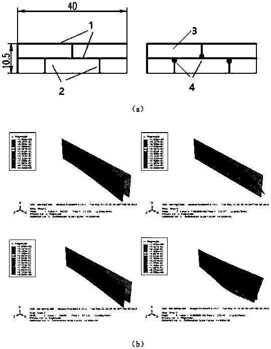
[0094] In the step (1), a model A is established, and the model A is a bionic wing skeleton structure. According to the topological distribution of the wing veins on an insect wing with a uniform distribution of the aspect ratio in the spanwise direction, a rectangul...
Embodiment 2
[0119] A finite element modeling method for a flexible bionic wing with spring elements, comprising at least the following steps:
[0120] (1) Establish model A and model B by drawing sketches and generating components;
[0121] (2) Give the components section properties and material parameters, respectively, to create assemblies;
[0122] (3) Set constraints and bind model A and model B to model C;
[0123] (4) Define the spring element, select the two-node spring element Spring2, and set the stiffness of each node in the direction of different degrees of freedom;
[0124] (5) Define analysis steps, set boundary conditions, apply loads, and divide meshes;
[0125] (6) Create a job and submit the calculation.
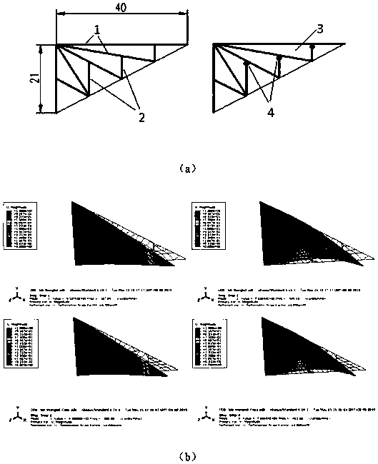
[0126] In the step (1), a model A is established, and the model A is a bionic wing skeleton structure. According to the topological distribution of the wing veins on the spanwise linearly reduced insect wings according to the aspect ratio, a triangular bionic wing skel...
Embodiment 3
[0151] A finite element modeling method for a flexible bionic wing with spring elements, comprising at least the following steps:
[0152] (1) Establish model A and model B by drawing sketches and generating components;
[0153] (2) Give the components section properties and material parameters, respectively, to create assemblies;
[0154] (3) Set constraints and bind model A and model B to model C;
[0155] (4) Define the spring element, select the two-node spring element Spring2, and set the stiffness of each node in the direction of different degrees of freedom;
[0156] (5) Define analysis steps, set boundary conditions, apply loads, and divide meshes;
[0157] (6) Create a job and submit the calculation.
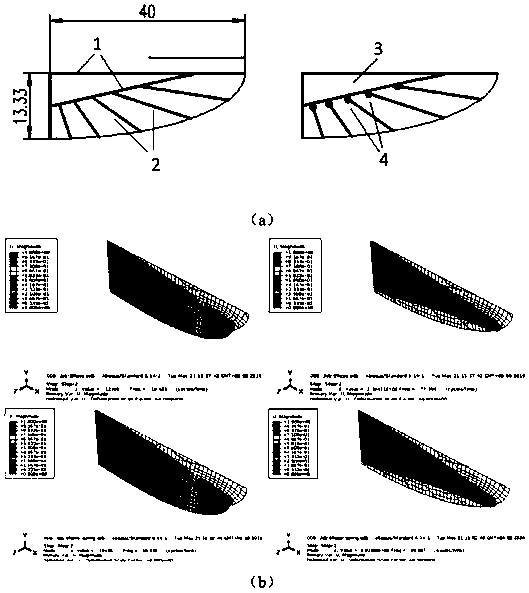
[0158] In the step (1), a model A is established, and the model A is a bionic wing skeleton structure, and a quarter elliptical bionic wing is drawn according to the topological distribution of the wing veins on the spanwise nonlinear reduced insect wings according t...
PUM
| Property | Measurement | Unit |
|---|---|---|
| Young's modulus | aaaaa | aaaaa |
| Density | aaaaa | aaaaa |
| Young's modulus | aaaaa | aaaaa |
Abstract
Description
Claims
Application Information