

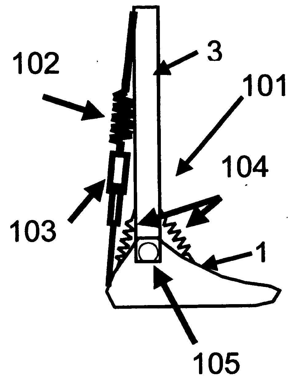
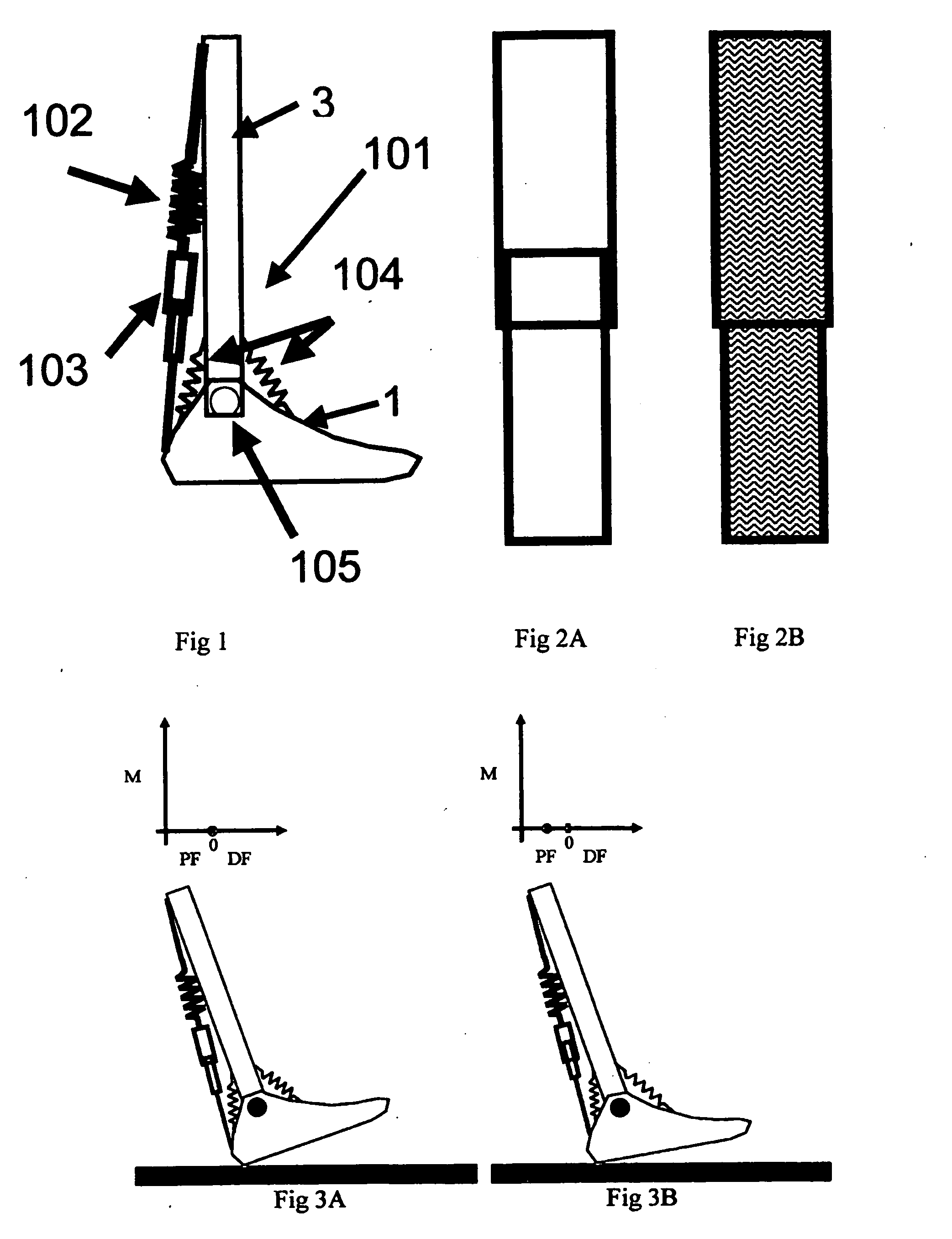
Equilibrium-point prosthetic and orthotic ankle-foot systems, devices, and methods of use
a technology of orthotic ankle and system, applied in the field of improvement of prosthetic systems, can solve the problems of compromising user's balance, affecting the use of users, and many currently available prosthetic and orthotic ankle-foot mechanisms that do not allow ankle motion, so as to prevent or reduce the likelihood of compromising users' balan
- Summary
- Abstract
- Description
- Claims
- Application Information
AI Technical Summary
Benefits of technology
Problems solved by technology
Method used
Image

Examples
example i
Use of Weight-Activation to Control the Ankle Mechanism
[0133]Engagement can be set to occur upon loading of the device by the user's weight. In this case, a mechanism is in place that engages the triceps surae torsional means after a sufficient amount of body weight has been applied to the system. Upon unloading of the device, the engagement reverses (that is the triceps surae spring is disengaged from the rest of the system). Examples of this type of engagement are shown in devices #2 and #3.
example ii
Use of Potentiometers or Encoders to Control Locking-Unlocking Mechanisms
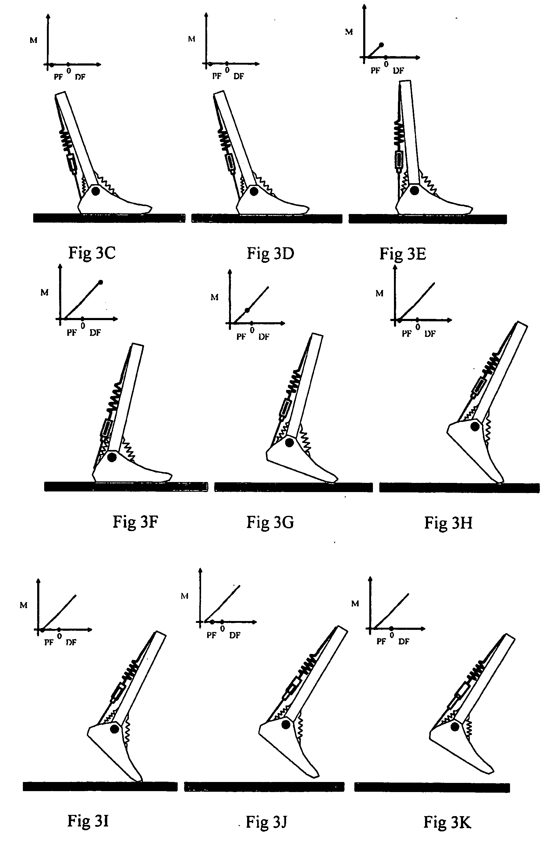
[0134]The projected ankle motion of this device is shown in FIG. 33. The potentiometers or encoders measure these angles during use of the device. In early stance, the locking mechanism may be unlocked. When the rotational sensor indicated that a minimum dorsiflexion angle is reached (at time 1), the system will signal to engage the locking mechanism. This mechanism remains engaged until this angle is approached at the end of stance phase (at time 2), at which time the system unlocks and allows the neutralizing springs to bring the ankle back to neutral for swing phase.
example iii
Use of Forefoot Pressure Sensors to Control Locking-Unlocking Mechanisms
[0135]An alternative way to control the locking and unlocking mechanism is to use a forefoot pressure sensor. In early stance, the ankle plantarflexes until the forefoot contacts the walking surface. At this first contact with the forefoot pressure sensor, the locking mechanism may be engaged. Forefoot contact remains until the toe comes off of the ground at the end of stance. At this time, the pressure goes to zero and the locking mechanism could be unlocked, allowing the neutralizing springs to bring the ankle back to neutral for swing phase.
PUM
 Abstract
Description
Claims
Application Information