
Method and apparatus for dispensing fluid compositions

Active Publication Date: 2010-07-22
ACCESS BUSINESS GRP INT LLC
View PDF37 Cites 79 Cited by
  • Summary
  • Abstract
  • Description
  • Claims
  • Application Information

AI Technical Summary

Benefits of technology

[0006]The present invention provides a miniaturized fluid composition dispenser capable of accurately combining a plurality of constituent fluids. The dispenser generally includes a plurality of fluid reservoirs containing a plurality of different constituent fluids, a plurality of pumps for moving fluids through the dispenser, a motor for driving the pumps, a valve assembly for recirculating or discharging fluid from the fluid reservoirs to an outlet and a control system for controlling the constituents of a dispensed fluid composition.
[0008]In one embodiment, the valves may be actuated electromagnetically. For example, in one embodiment, the valve may include a magnetic moving member that is moved between outlet and recirculation positions through the selective application of electromagnetic fields. The valve may include a pair of electromagnetic coils disposed on opposite sides of the moving member. In use, power may be selectively applied to the coils to actuate the moving member. The coils may be configured with opposite polarity such that they operate in a push / pull arrangement. Using cooperative action, the overall size of the coils required to operate the moving member is reduced.

Problems solved by technology

However, even as the number of available choices has increased, the user's choice is limited by the availability of pre-manufactured mixtures.
However, many conventional fluid distribution systems include a variety of limitations that impede use in customized and miniaturized applications.
For example, manually operated positive displacement pumps do not dispense product with the degree of precision required to generate customized fluids of the desired tone, shade or hue.
Additionally, electro-mechanically operated dispensers often require multiple motors for operation of valve and pump assemblies, often comprising a dispenser that cannot be conveniently stored in a purse or handbag.

Method used


Image

  • Method and apparatus for dispensing fluid compositions
  • Method and apparatus for dispensing fluid compositions
  • Method and apparatus for dispensing fluid compositions

Examples


Embodiment Construction

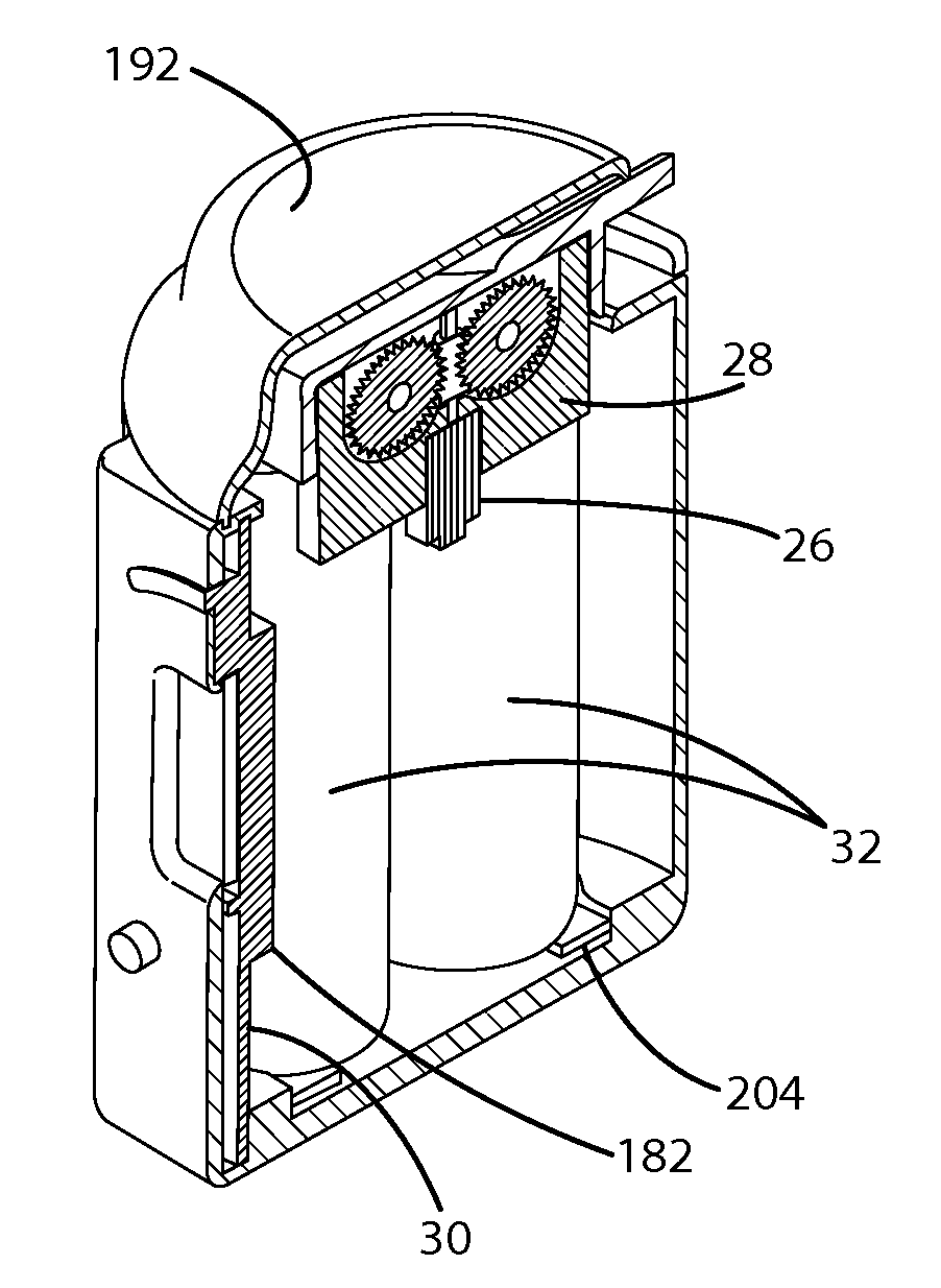
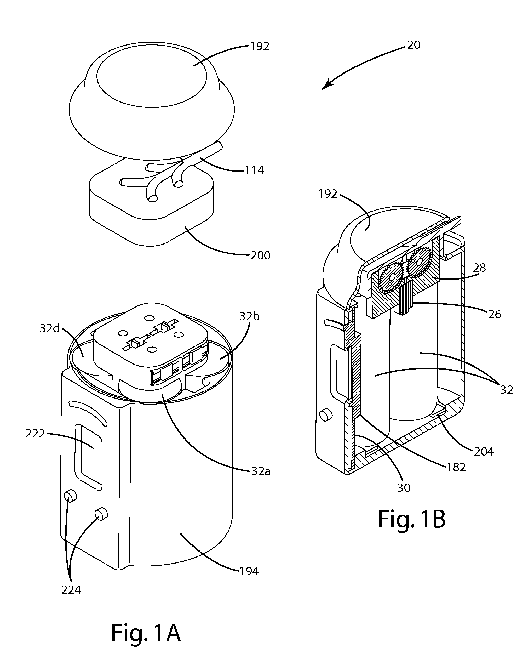
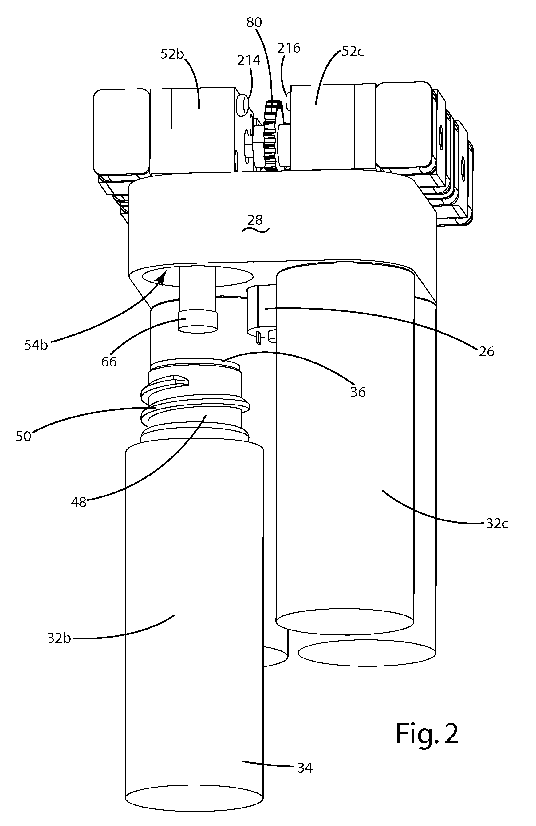
[0029]A fluid composition dispenser 20 in accordance with an embodiment of the present invention is shown in FIG. 1A. The embodiment shown in FIG. 1A is adapted for use as a handheld dispenser ideal for cosmetic and skin care fluid compositions. The dispenser 20 may be used to generate medical, cosmetic or nutritional fluids for topical or systemic application and having varying compositions over the course of a treatment regimen. Additionally, the dispenser 20 may be used to generate personalized fluid compositions of a desired formula based on user-supplied input, including known allergies and prior skin reactions. The present invention is, however, well suited for use in other applications where miniaturized fluid blending and dispensing is desired. For example, the fluid dispenser 20 may also be used to combine vitamins, supplements and flavors in water to create a consumable beverage or food supplement.

[0030]The fluid dispenser of FIG. 1A generally includes a plurality of fluid...


PUM


Abstract

A miniaturized fluid dispensing system for dispensing customized fluids. The dispenser may include first and second reservoirs containing constituent fluids; a drive motor; at least two pump assemblies commonly driven by the drive motor and in communication with the first and second reservoirs; first and second valve assembly in communication with the first and second pump assemblies; and a control system for selectively controlling the valve assemblies to blend and discharge a composition from the constituent fluids. The system may include a dispensing header to house the valves and to define ‘discharge’ and ‘recirculation’ flow paths for each constituent fluid. The present invention also provides a method for dispensing a fluid regimen (e.g. a plurality of compositions) by periodically blending and discharging varying compositions over time.

Description

BACKGROUND OF THE INVENTION[0001]The present invention relates to fluid distribution systems, and more particularly to portable systems for dispensing fluid compositions.[0002]Various fluid dispensers and methods for mixing and metering small quantities of fluid are well known in the prior art. Generally, fluid dispensers and associated methods have included a first stage for storing two or more fluids, a second stage for selectively mixing the fluids, and a third stage for dispensing a product containing the fluids in desired proportions. In miniaturized or portable applications, fluid dispensers have included replaceable fluid reservoirs and a small, internal energy supply for powering the miniaturized device. An example of a miniaturized fluid dispensing system is disclosed in U.S. Pat. No. 5,709,317 to Bertram et al.[0003]In certain applications, for example the use of cosmetic products, there remains a significant and increasing interest in improved miniaturized dispenser syste...

Claims


Application Information

Patent Timeline
IPC IPC(8): G05D11/13A45D40/00B67D5/56
CPCA45D34/00A45D34/04A45D40/24A45D2200/058A61M5/1413A61M5/14236A61M5/16827A61M35/003B01F13/002B01F13/1055B01F13/1063B01F13/1066B01F15/00123B01F15/00155B01F15/00305B01F15/0429B01F15/0479B01F2215/0031B01F2215/0034F04C2/14F04C11/001F04C2220/24F04C2270/90B01F33/5011B01F33/8442B01F33/846B01F33/84B01F35/2112B01F35/20B01F35/2205B01F35/833B01F35/883B01F2101/2202B01F2101/21
Inventor BYLSMA, RICHARD B.BAARMAN, DAVID W.MARSHALL, MARK G.BECKER, PIERRE
Owner ACCESS BUSINESS GRP INT LLC
Learn More