Truck compartment verification system with alternate truck id

a verification system and truck compartment technology, applied in liquid transfer devices, process and machine control, instruments, etc., can solve the problems of large amount of sensors to be connected, difficult to identify, and complex monitoring process of controllers

Active Publication Date: 2010-07-22
SCULLY SIGNAL CO
View PDF17 Cites 14 Cited by
  • Summary
  • Abstract
  • Description
  • Claims
  • Application Information

AI Technical Summary

Problems solved by technology

This can be particularly problematic for trucks having a large amount of compartments and thereby requiring a large amount of sensors to be connected, since the number of pins provided on a standard connection socket may not be sufficient.
However, the monitoring process of the controller is more complex, since it is difficult to identify which of the daisy chained sensors is detecting an overfill condition.
Moreover, unlike with the two wire sensor, malfunctioning sensors can very easily be bypassed, leaving the compartment of the sensor unprotected from possible overfills.
One problem with sensors connected in series is that a malfunctioning sensor can easily be bypassed without the controller detecting the bypass.
It is possible to bypass a malfunctioning sensor 110 by connecting the pulse output of the previous sensor to the pulse input of the next sensor, such as illustrated in FIG. 1c. Since the bypassed sensor no longer has an effect on the propagation of the detection pulse, there is a possibility for the filling operations to continue, causing an overfill and spill.
This creates a potentially dangerous situation, where spillage of fluids such as hazardous or flammable fluids can cause fatal accidents.
In large and dynamic fleets this reprogramming of racks becomes burdensome.
Such reallocation necessitates the reprogramming of controllers to delete or add new TIDs from the racks—a costly and inefficient process.

Method used


Image

  • Truck compartment verification system with alternate truck id
  • Truck compartment verification system with alternate truck id
  • Truck compartment verification system with alternate truck id

Examples


Embodiment Construction

[0031]This application claims priority from, and incorporates by reference for all purposes, the entirety of, U.S. Provisional Application No. 61 / 145,253, entitled “Fluid Overfill Detection and Control System With Sensor Count Verification” and which was filed Jan. 16, 2009.

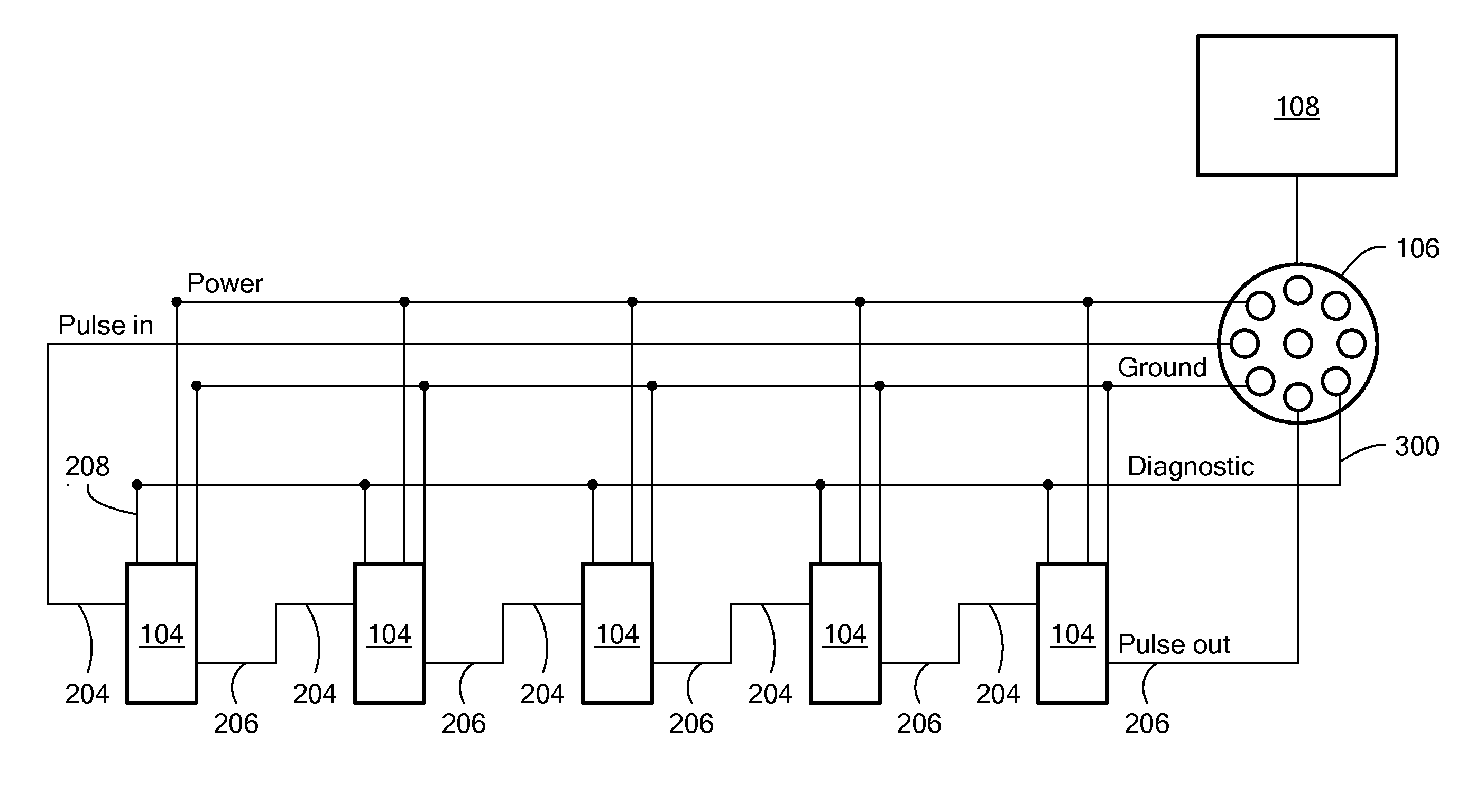
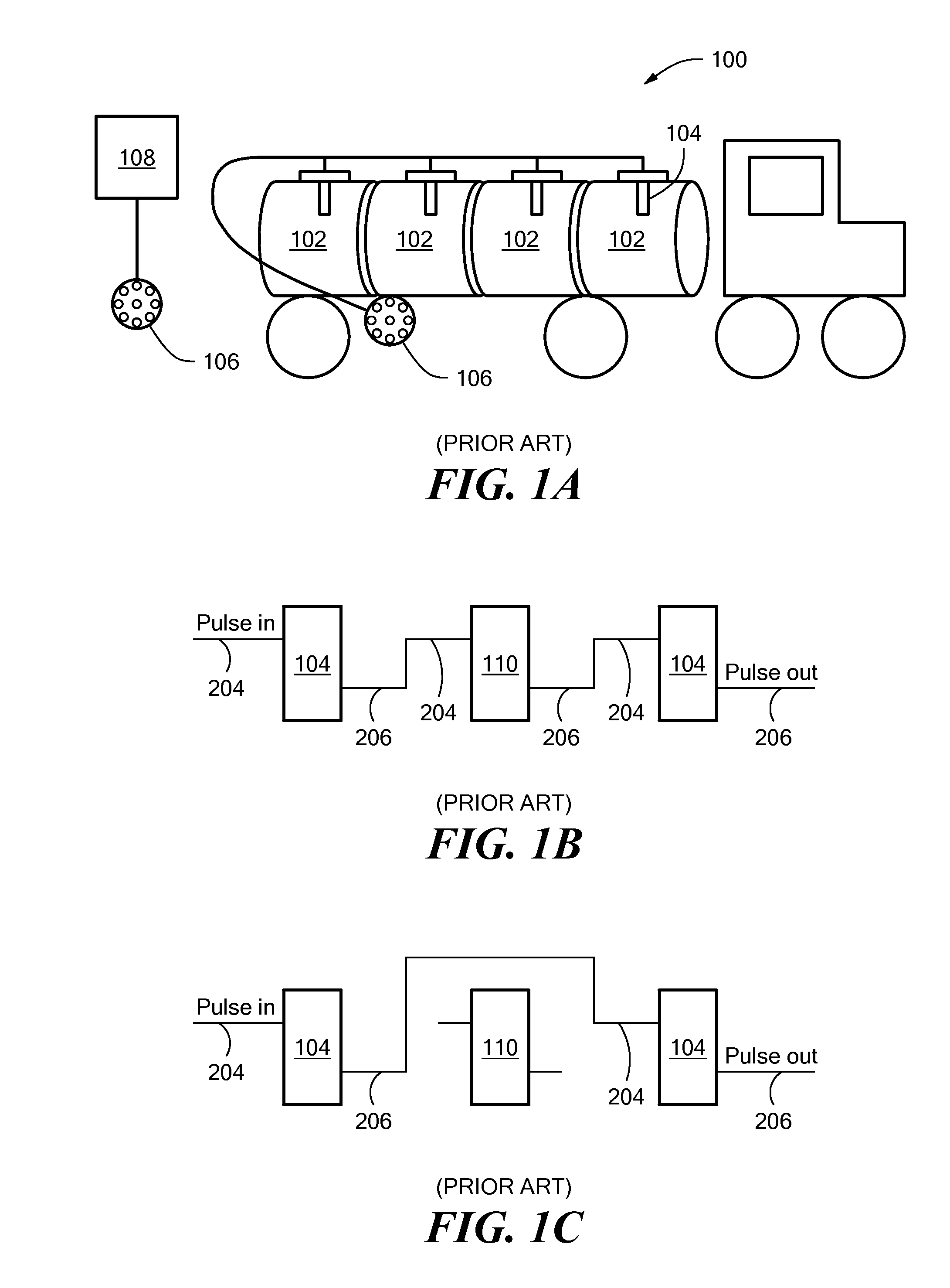
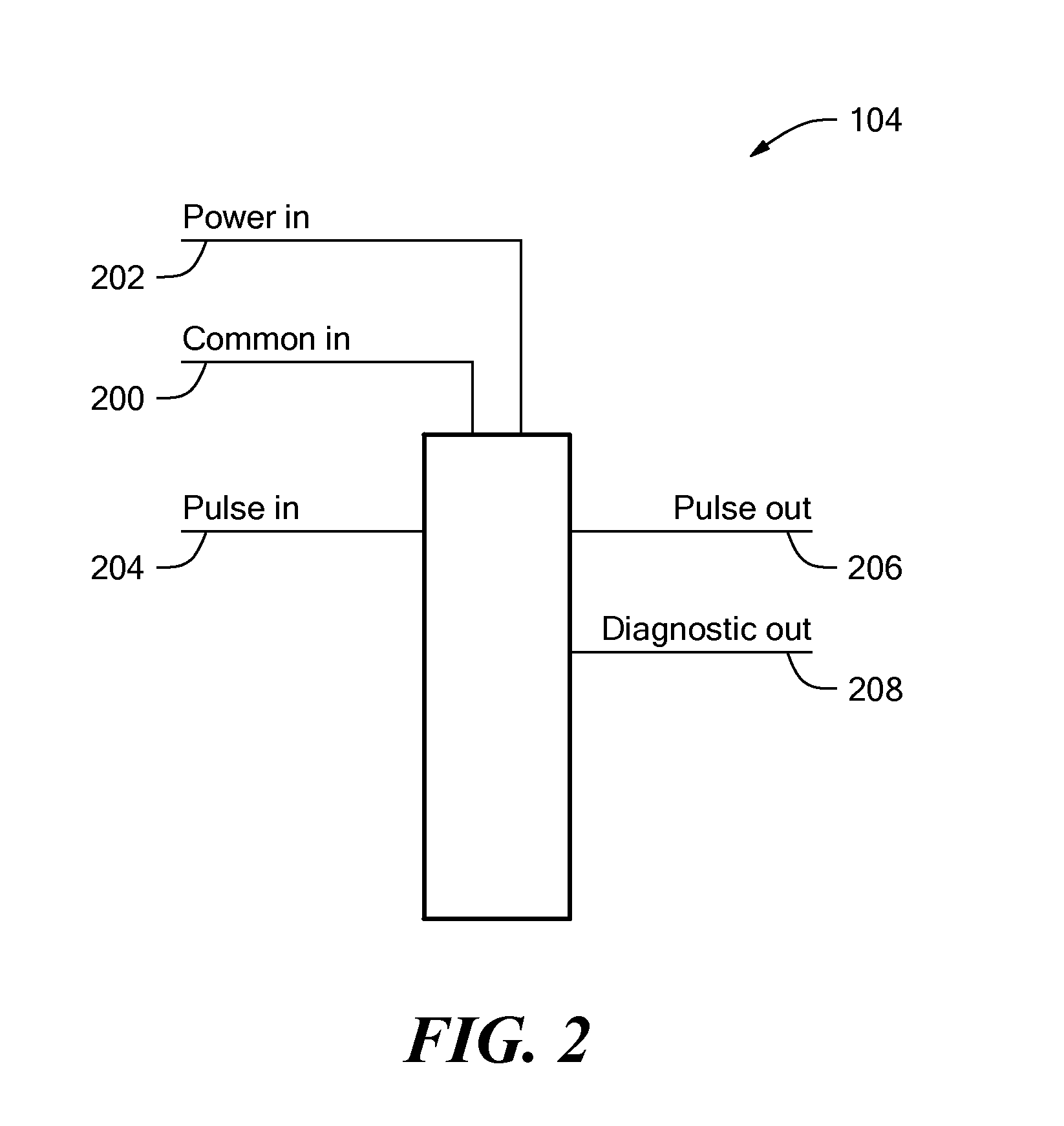
[0032]Embodiments of the present invention relate to an overfill detection and control system that uses sensors 104 such as those shown in FIG. 1a. The sensors 104 each have a conical prism which receives light from a light emitting diode (LED). When activated, the LED emits a light beam into the prism towards an interface between the prism and the external environment. The angle of the interface is such that, when the prism is in contact with air (i.e., sensor is “dry”), the light beam is internally reflected within the prism due to the difference in the refractive index of the air and the prism material, and is directed toward a phototransistor. The phototransistor generates an electrical pulse in response to a...


PUM


Abstract

A fluid overfill detection and control system for controlling the transfer of fluid into a transport vehicle having multiple fluid compartments includes a plurality of overfill sensors that are connected in series with one another and that each produces an output pulse when the fluid level in its associated compartment is below a threshold level. A diagnostic line connected to each of the overfill sensors provides a diagnostic signal indicative of the number of overfill sensors that generate an output pulse, while a module on the vehicle provides an indication of the total number of overfill sensors located in the vehicle. To prevent a hazard due to the possible bypass of a overfill sensor, the controller compares the overfill sensor count signal to the diagnostic signal and inhibits the transfer of fluid into the vehicle if the values do not match.

Description

FIELD OF THE INVENTION[0001]The present invention relates to fluid overfill detectors and control systems in fluid transportation vehicles. In particular, embodiments of this invention relate to the field of flammable fluid transfers in transportation vehicles.BACKGROUND OF THE INVENTION[0002]Controlling the safe and proper transfer of flammable fluids when loading transportation vehicles such as tanker trucks has long been a concern in the petroleum industry. In recent years, safety devices have been implemented on tanker trucks that prevent fluid transfer from a loading terminal to the truck if certain unsafe conditions surrounding the transfer exist. These devices use detection equipment to determine if all of the safety precautions have been taken and prevent fluid flow if they have not. The prevention of fluid flow is controlled electrically, by closing a valve in a fluid transfer conduit, or by disabling a pump that is responsible for transferring the fluid to the tanker.[0003...

Claims


Application Information

Patent Timeline
Patent Type & Authority Applications(United States)
IPC IPC(8): G05D9/12G05D7/06
CPCB67D7/3209B67D7/362G01F23/2925G01F23/2927G01F25/0076Y10T137/7287Y10T137/7306G01F25/24
Inventor TROTTIER, ROBERT R.LANGLAIS, KENNETH L.
Owner SCULLY SIGNAL CO
Why Eureka
Try Eureka