Aerial payload deployment method

a technology of payload and deployment method, which is applied in the direction of fluid pressure measurement by mechanical elements, navigation instruments, special data processing applications, etc., can solve the problems of long delay time, inability to deploy surveillance helicopters in time, and inability to meet the needs of small police and public safety departments

Inactive Publication Date: 2010-07-22
SOFCOAST
View PDF5 Cites 17 Cited by
  • Summary
  • Abstract
  • Description
  • Claims
  • Application Information

AI Technical Summary

Benefits of technology

[0010]In another embodiment, the aerial platform may comprise a torque stabilization system having upper and lower vertical stabilizers with corresponding vertical stabilizer shroud fixtures along the upper and lower aft section of the outer shell surface of the system to provide for directional stability along the longitudinal axes of the system during flight.

Problems solved by technology

Smaller police and public safety departments usually cannot afford the cost of a department specific helicopter.
Accordingly, it can take hours to deploy a surveillance helicopter.
These long delay times can be detrimental to the immediate need for surveillance response to situations like crime scenes, high speed chases and amber alerts.
However, these devices and systems often remain cost prohibitive.
Additionally, many conventional systems require extended training in use, or require multiple personnel to deploy.
These additional costs further prevent their implementation in smaller police or other public safety departments.

Method used


Image

  • Aerial payload deployment method
  • Aerial payload deployment method
  • Aerial payload deployment method

Examples


Embodiment Construction

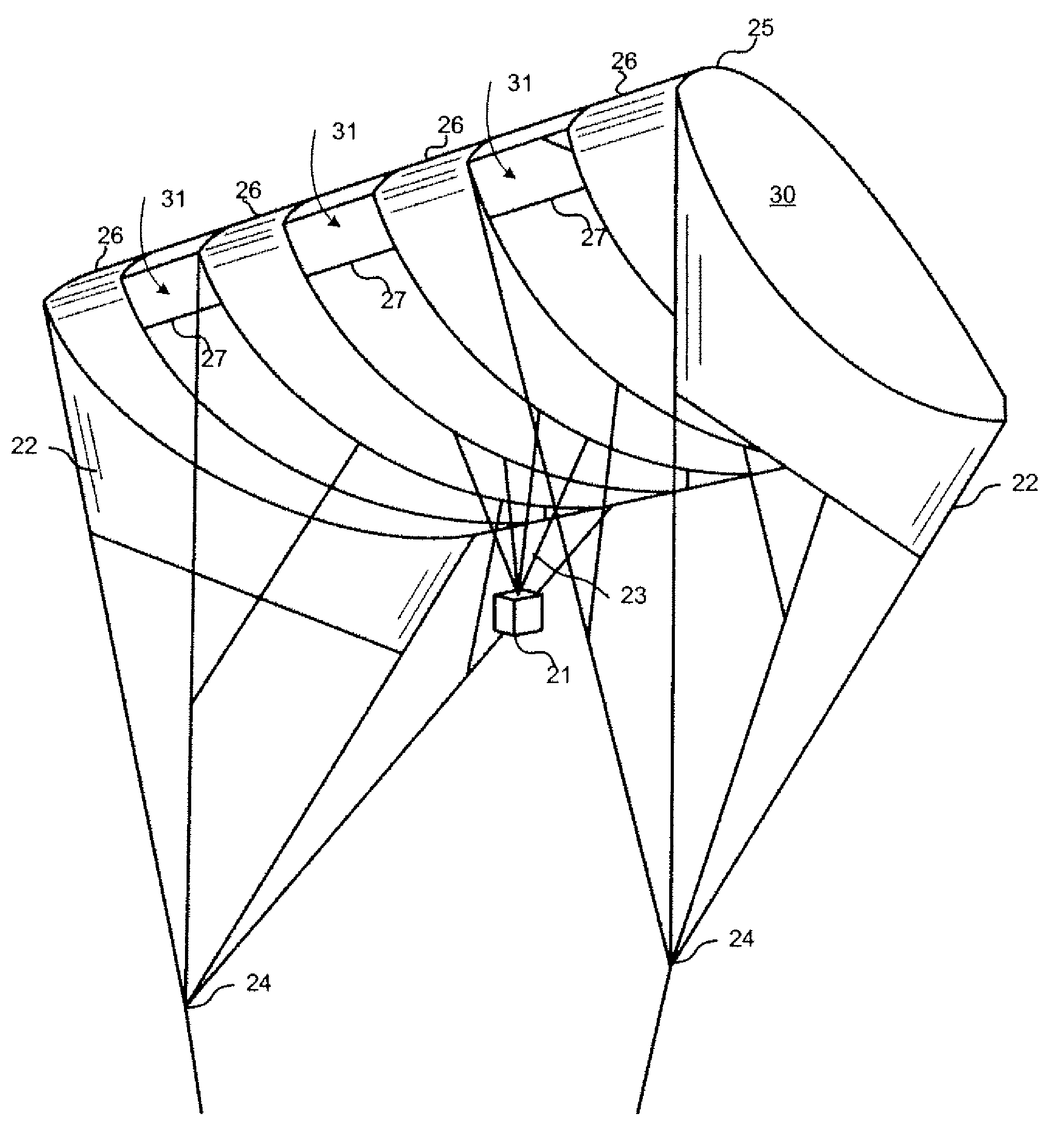
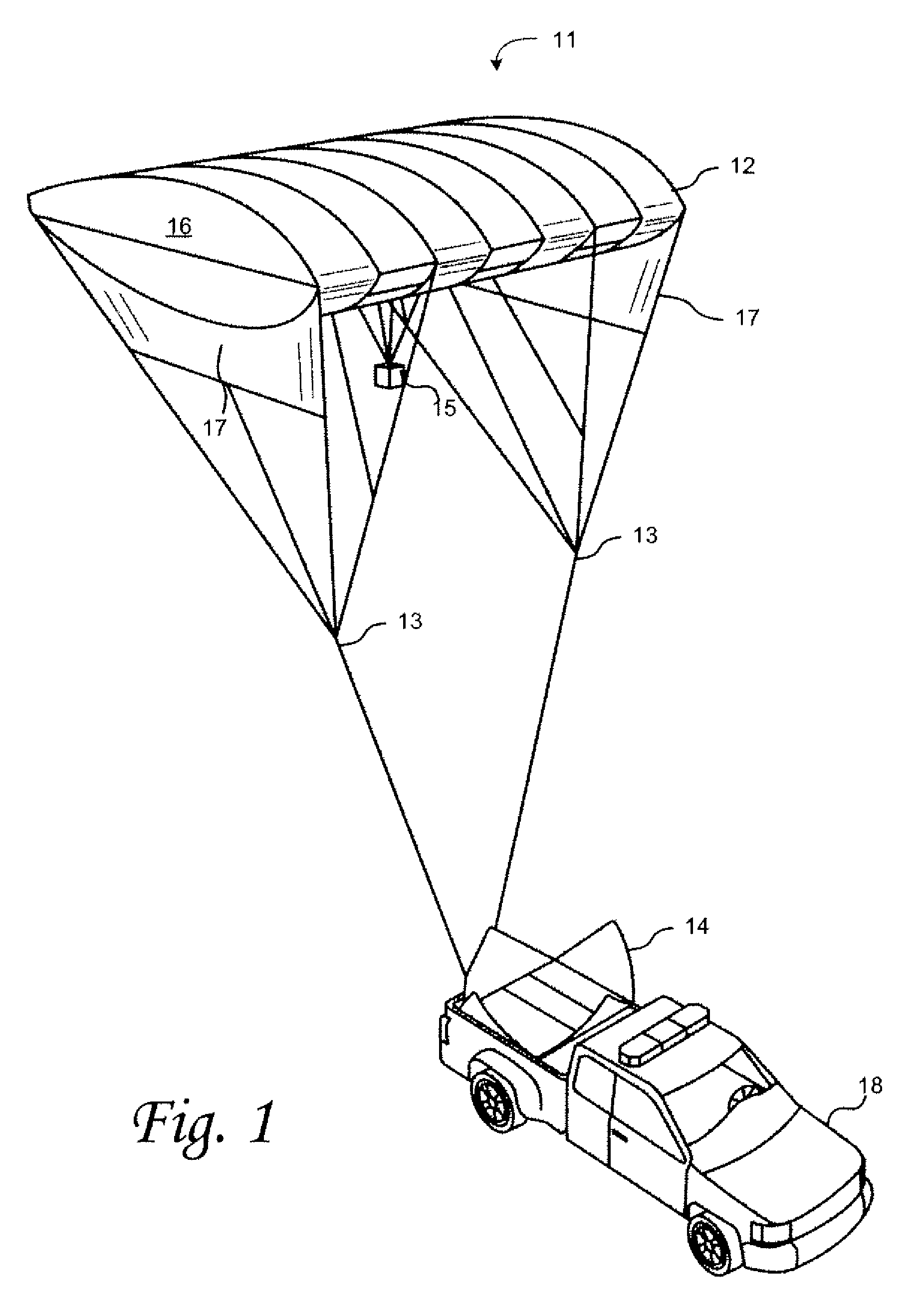
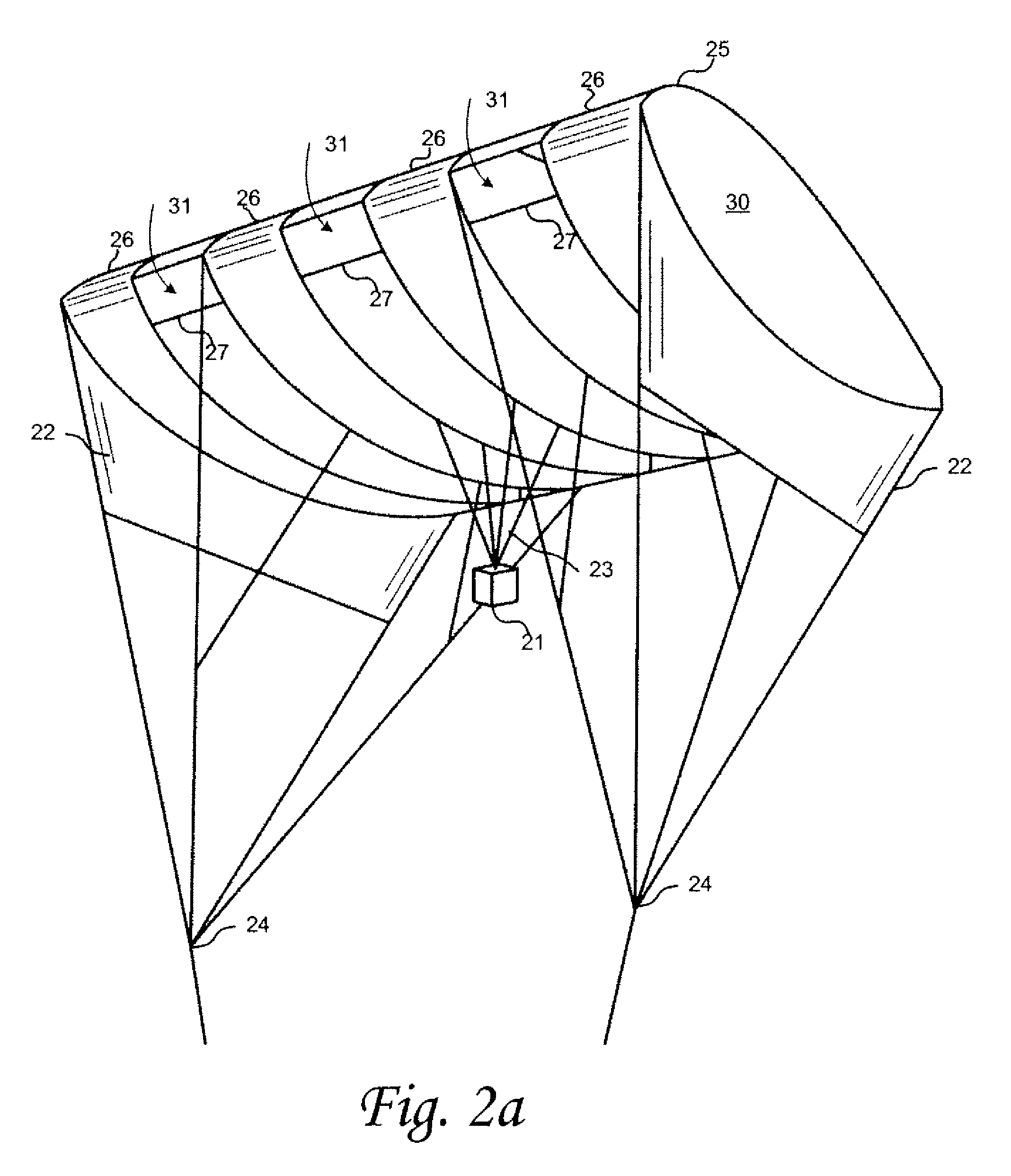
[0005]According to various embodiments of the invention, a mobile aerial platform system is provided. The system may lift a payload, such as a surveillance system or a communications repeater, into the lower atmosphere to assist in providing command and control functions such as communications, surveillance, crowd control and disaster relief. The portable aerial platform system may be transported to the deployment site using a vehicle.

[0006]In one embodiment, a method comprises: providing an aerial platform having an outer shell; disposing a gas containment system within the outer shell; attaching the aerial platform to an object using a tether system; and inflating the aerial platform and lifting a payload; wherein the aerial platform is configured such that it may be completely collapsed when deployed.

[0007]In some embodiments, the aerial platform comprises an outer shell that provides an aerodynamic shape to effect desired flight performance characteristics.

[0008]According to a f...


PUM


Abstract

The present invention provides a method, comprising: providing an aerial platform having an outer shell; disposing a gas containment system within the outer shell; attaching the aerial platform to an object using a tether system; and inflating the aerial platform and lifting a payload; wherein the aerial platform is configured such that it may be completely collapsed when deployed.

Description

CROSS-REFERENCE TO RELATED APPLICATIONS[0001]This application claims priority to U.S. Provisional Patent Application Ser. No. 61 / 146,251 filed Jan. 21, 2009, the content of which is incorporated herein by reference in its entirety.TECHNICAL FIELD[0002]The present invention relates to aerial electronics deployment, and more particularly, some embodiments relate to portable aerostat deployment systems.DESCRIPTION OF THE RELATED ART[0003]In large metropolitan areas, police departments and other public safety departments frequently use helicopters to fulfill their mobile surveillance needs. Smaller police and public safety departments usually cannot afford the cost of a department specific helicopter. Therefore, departments must frequently share access to a helicopter amongst themselves, or between departments in different cities. Accordingly, it can take hours to deploy a surveillance helicopter. These long delay times can be detrimental to the immediate need for surveillance response ...

Claims


Application Information

Patent Timeline
Patent Type & Authority Applications(United States)
IPC IPC(8): B64B1/50G06F17/00H04B7/15G06F19/00
CPCB64B1/06B64B1/50B64C2201/022B64C2201/101B64C2201/127B64C2201/148H04B7/18504B64C2201/208B64B2201/00B64U10/30B64U2201/202B64U80/86B64U2101/30
Inventor SURMONT, JOHN STEVEN
Owner SOFCOAST
Why Eureka
Try Eureka