
Trolling motor lock assembly

Inactive Publication Date: 2010-07-29
FRANTZ DONALD R
View PDF15 Cites 2 Cited by
  • Summary
  • Abstract
  • Description
  • Claims
  • Application Information

AI Technical Summary

Benefits of technology

[0003]In the view of this inventor, what is needed is a unitary, one-piece device or assembly for securely and inexpensively locking a trolling motor to the boat that it is attached to. The present invention provides such an assembly that, when used properly, helps to prevent inadvertent detachment or intentional theft of the trolling motor at all times during which the assembly is used. The present invention provides for a unique locking assembly having a number of components that form such a unitary device. The assembly includes a longitudinally extending base member that is attached via a hinge to a longitudinally extending cover member. The base member and the cover member, when rotated such that the cover member engages the base member, are functionally adapted to overlay the head portion of the clamping screws of the motor supports of the trolling motor thereby preventing rotation of them. The base member and the cover member each have a plurality of cooperating cut-outs defined in adjacent side-walls that allow the shaft of each of the clamping screws to protrude through the cut-outs. In that way, the base member and the cover member may be “clamped” down over the head portions of the clamping screws. The base member and the cover member also include a cooperating catch and cylinder lock with a rotatable latch, respectively, whereby the base member and the cover member may be locked together to secure the head portions of the clamping screws between them. The foregoing and other features of the assembly of the present invention will be apparent from the detailed description that follows.

Problems solved by technology

During use, these clamps can be inadvertently bumped or rotated to the point that the trolling motor is not completely secured to the transom.
Another unfortunate reality concerning trolling motors is that the motors are vulnerable to theft since they are relatively small and light-weight and, as such, can be quickly and easily detached from the boat.
However, the prior art discloses devices or assemblies that comprise a number of separate parts or members, thus risking a lack of functionality if any one or more of those parts or members is separated from the others.

Method used


Image

  • Trolling motor lock assembly
  • Trolling motor lock assembly
  • Trolling motor lock assembly

Examples


Embodiment Construction

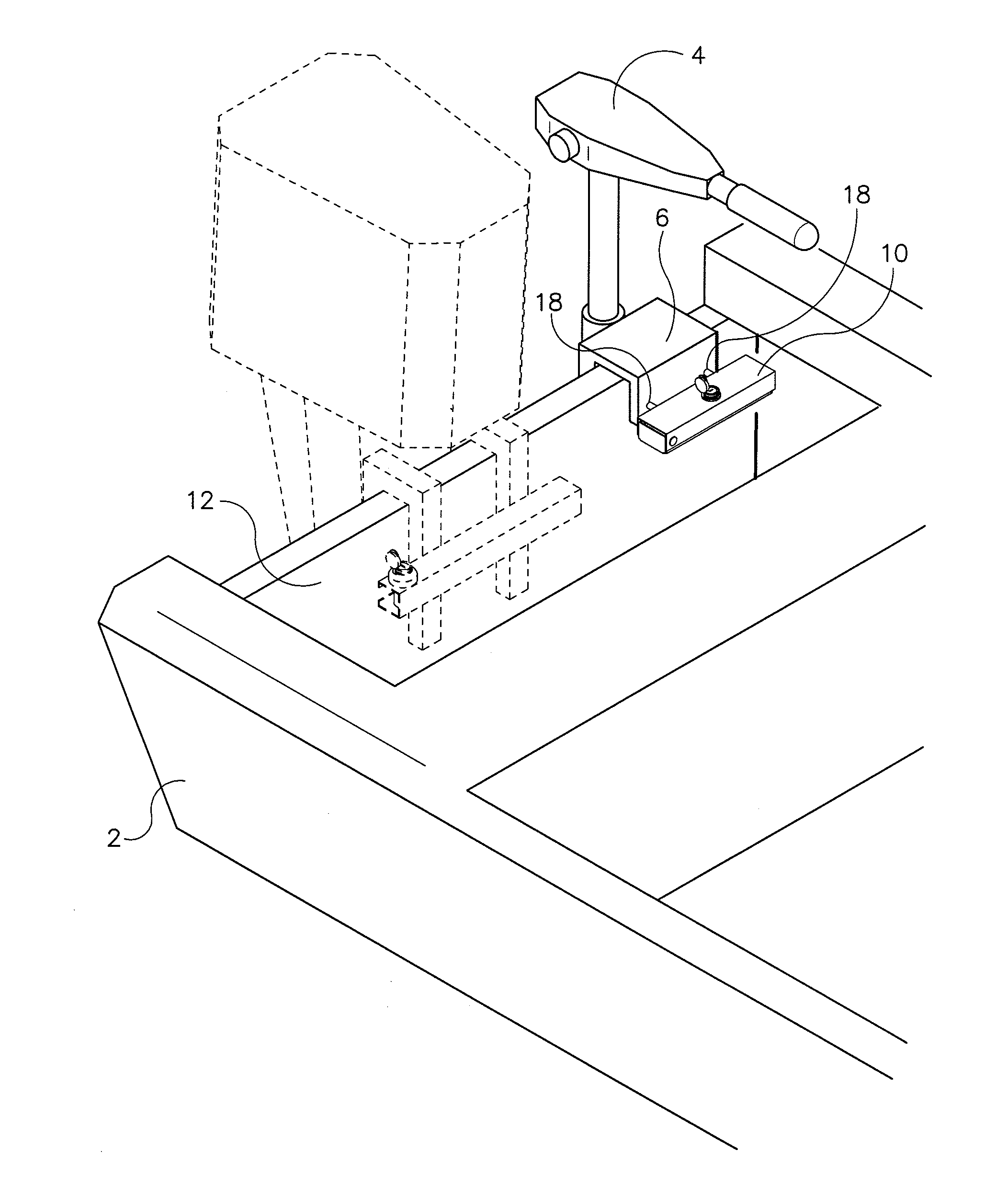
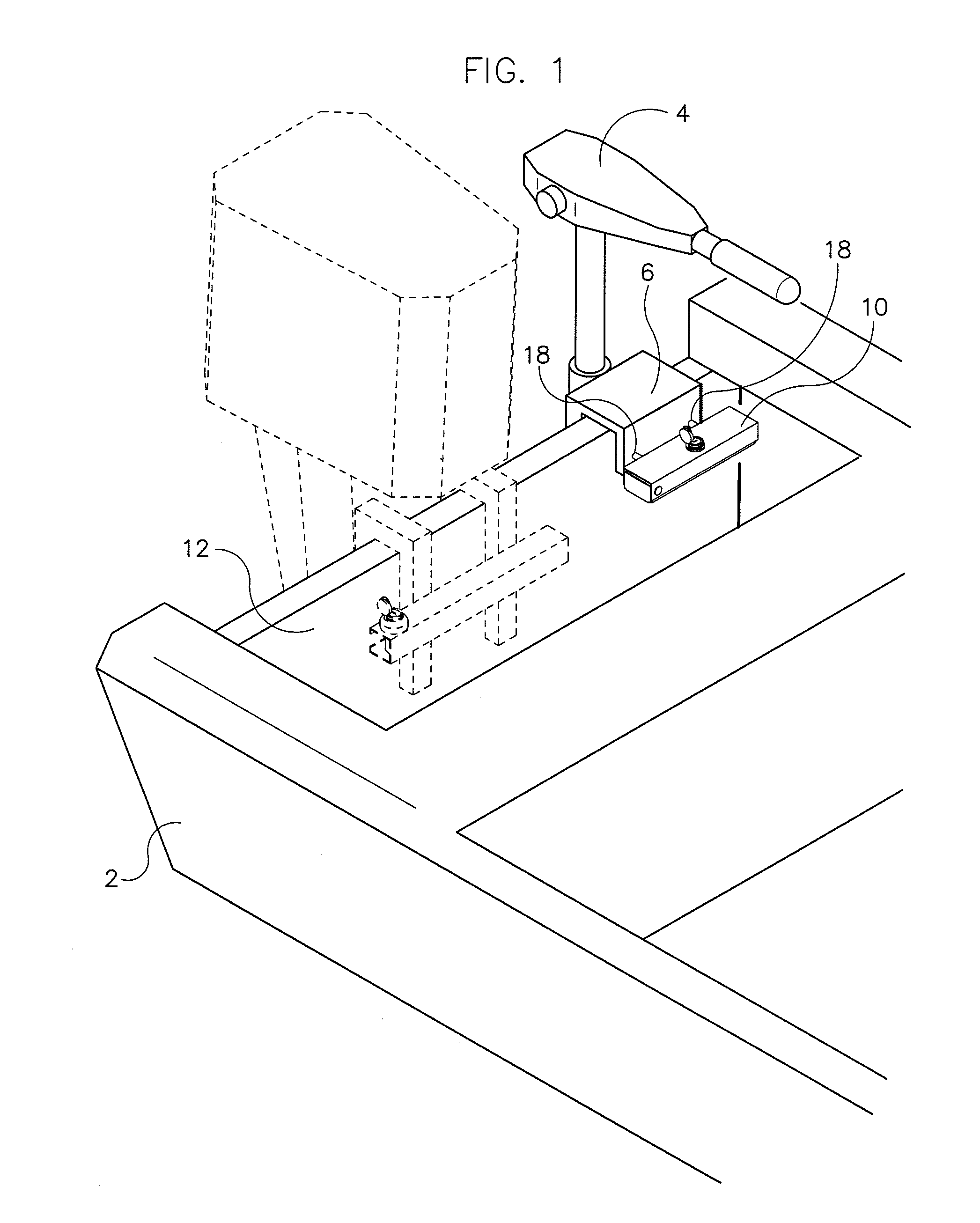
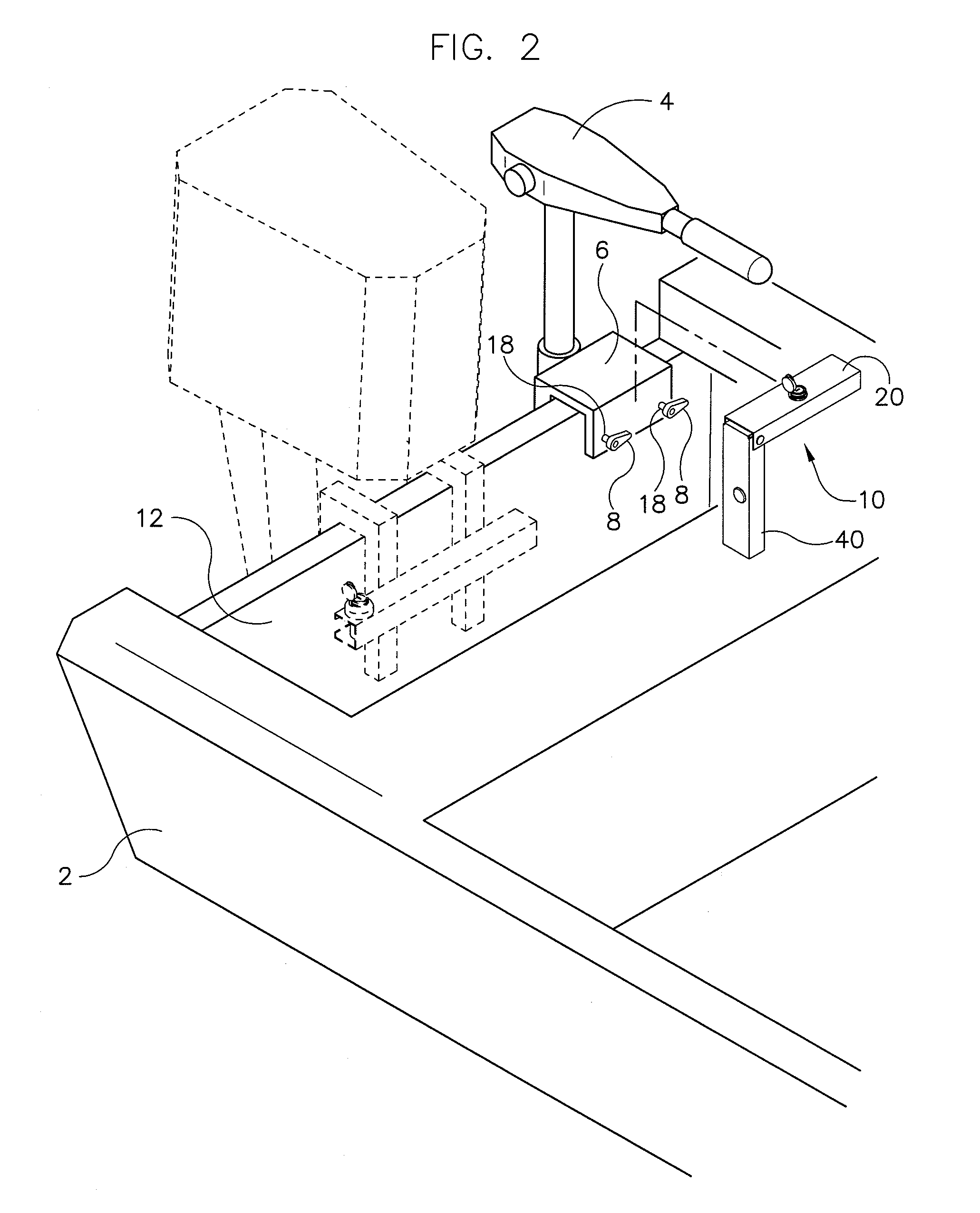
[0010]Referring now to the drawings in detail, wherein like numbered elements correspond to like elements throughout, FIG. 1 is a perspective view showing a preferred embodiment of the trolling motor lock assembly, generally identified 10, that is constructed in accordance with the present invention. An outboard motor is illustrated in phantom view in both FIGS. 1 and 2 to demonstrate how a trolling motor 4 might be used in conjunction with it. Such is not, however, required and is in no way a limitation of the present invention.

[0011]As shown, the trolling motor lock assembly 10 is shown as it would be attached to the head portions 8 of clamping screws 18 of the motor supports of the trolling motor 4 when the trolling motor 4 is secured to the transom 12 of a boat 2. See also FIG. 2 which illustrates the assembly 10 as it would appear when removed from the head portions 8 of the clamping screws 18. It is to be understood that the precise type of boat 2 or trolling motor 4 to which ...


PUM


Abstract

A trolling motor lock assembly (10) has base member (40) that is attached via a hinge (70) to a cover member (20). The base member (40) and the cover member (20), when rotated such that the cover member (20) engages the base member (40), overlay the head portion (8) of the clamping screws (18) of the motor support (6) of the trolling motor (4) preventing rotation of them. The base member (40) and the cover member (20) have cooperating cut-outs (31, 33, 35, 51, 53, 55) adjacent side-walls (25, 45) that allow the shaft of the clamping screws (18) to protrude through the cut-outs (31, 33, 35, 51, 53, 55). In that way, the base member (40) and the cover member (20) may be “clamped” down over the head portions (8) of the clamping screws (18). The base member (40) and the cover member (20) also include a cooperating catch (67) and cylinder lock (62) with a rotatable latch (65), respectively, whereby the base member (40) and the cover member (20) may be locked together to secure the head portions (8) of the clamping screws (18) between them.

Description

FIELD OF THE INVENTION[0001]The present invention relates generally to locks and to other security devices that use locks and locking mechanisms. More specifically, it relates to an assembly that is used to secure a trolling motor to the transom of a boat. It also relates to such a trolling motor lock assembly that is unitary in construction such that the assembly is easy to use and eliminates the risk of loss of component parts.BACKGROUND OF THE INVENTION[0002]Trolling motors are the smaller cousin to the boat outboard motor and are used in situations where a smaller powered motor is needed to achieve more incremental and much quieter movement of the boat during fishing and the like. Like outboard motors, the use of a trolling motor typically requires that the motor be attached to the transom, or rear wall, of the boat. From that position, the user can move and steer the boat using the controls of the trolling motor. Such trolling motors often utilize a U-shaped frame that hangs on...

Claims


Application Information

Patent Timeline
IPC IPC(8): E05B65/12
CPCB63B2017/0009B63H20/007B63J99/00E05B73/0076Y10T70/5611
Inventor FRANTZ, DONALD R.
Owner FRANTZ DONALD R
Learn More