Shift control device for automatic transmission

a technology of automatic transmission and control device, which is applied in the direction of mechanical equipment, gearing details, transportation and packaging, etc., can solve the problems of low clutch burnout, heat generation, and hardly possible to ensure the lubrication of the clutch, so as to prevent burnout or burnout effectively, prevent the deterioration of the friction of the low clutch, and simple configuration

Inactive Publication Date: 2010-07-29
HONDA MOTOR CO LTD
View PDF0 Cites 13 Cited by
  • Summary
  • Abstract
  • Description
  • Claims
  • Application Information

AI Technical Summary

Benefits of technology

[0026]According to the present invention, by addition of a simple configuration (for example, addition of a port to the shift valve or the like), it is possible to supply the sufficient amount of lubricating oil with line pressure to the low clutch in a situation in which temperature around the low clutch rises. This makes it possible to effectively prevent burn-in (or burnout) of the low clutch due to drag of the low clutch at pseudo neutral control, in particular. Further, when the amount of lubricating oil for the low clutch is enough, it is possible to prevent deterioration of friction of the low clutch due to increase in the amount of lubricating oil by stopping supply of the lubricating oil with the line pressure.

Problems solved by technology

For this reason, at a state where the number of revolutions of the engine is low (small), for example, at idling of the engine, the regulator valve is not opened, whereby it is hardly possible to ensure lubrication of the clutches and the like.
In particular, at neutral idle control in which the automatic transmission is controlled so as to become a pseudo neutral state under a predetermined condition when a shift position is set to a forward (drive) range (D position), drag of a low clutch tends to cause heat to be generated.
Therefore, a problem appears that the low clutch is burned out if sufficient lubrication is not obtained.
However, in such a case, since the automatic transmission is in a state where flow of the hydraulic oil into the lubricating oil passage through the orifice with the minor diameter is always carried out, the amount of lubricating oil is too much at a normal drive mode.
Therefore, there is also a problem that this negatively affects friction and the like of the automatic transmission.

Method used


Image

  • Shift control device for automatic transmission
  • Shift control device for automatic transmission
  • Shift control device for automatic transmission

Examples


first embodiment

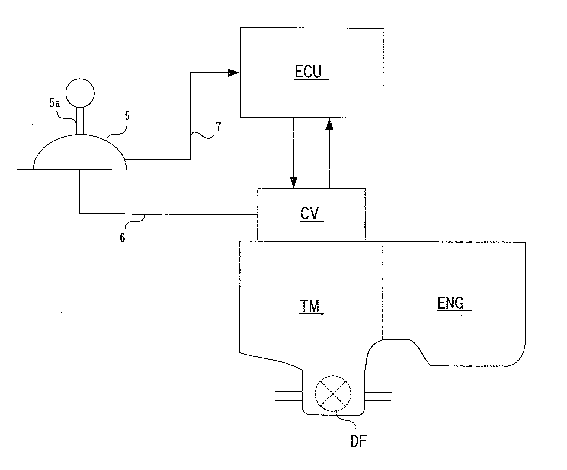
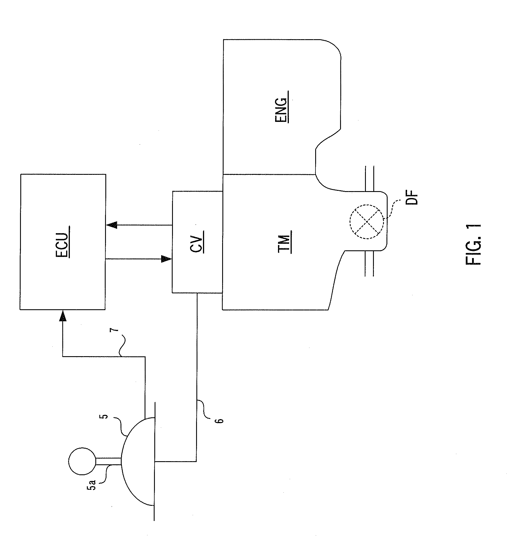
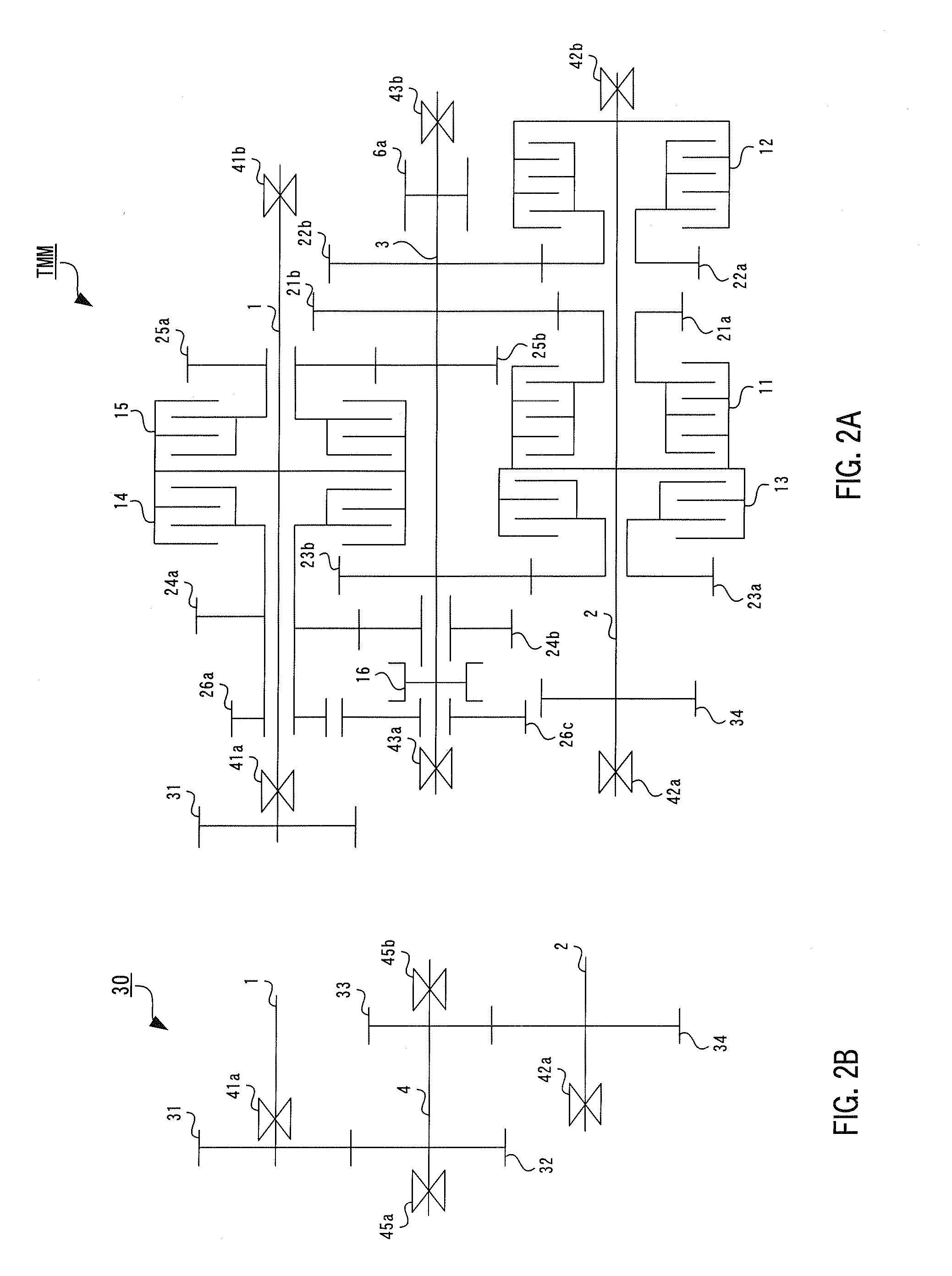
[0037]A shift control device for an automatic transmission according to a first embodiment of the present invention will now be described in detail with reference to FIG. 1 to FIG. 6. The whole configuration of an automatic transmission according to the first embodiment of the present invention will first be described. FIG. 1 is a schematic block diagram showing the whole configuration of the shift control device according to the first embodiment of the present invention and the automatic transmission controlled by the shift control device. FIG. 2 is a skeleton diagram showing a power transmission system of a five-gear-speed automatic transmission whose shift is controlled by the shift control device according to the present invention.

[0038]In the present embodiment, a power transmission mechanism TMM is configured by an automatic transmission TM that changes an output of an engine ENG to transmit the changed output to drive wheels (not shown in the drawings). Shift control of this ...

second embodiment

[0110]Next, low clutch lubricating control of a shift control device for an automatic transmission TM according to a second embodiment of the present invention will be described in detail with reference to FIG. 7. FIG. 7 is a part of a schematic hydraulic circuit diagram according to the second embodiment of the present invention. In this regard, the same reference numerals are assigned to constituent elements similar to or the same as those in the first embodiment, its detailed explanation is omitted, and differences from the first embodiment will be explained mainly. FIG. 7 mainly shows, as well as FIG. 5, hydraulic oil passages for supplying hydraulic oil to a low clutch 11, and constituent elements related to first and second lubricating oil passages for supplying lubricating oil, and other oil passages and valves are omitted in FIG. 7.

[0111]The hydraulic circuit according to the second embodiment is different from the hydraulic circuit according to the first embodiment describe...

third embodiment

[0114]Next, low clutch lubricating control of a shift control device for an automatic transmission TM according to a third embodiment of the present invention will be described in detail with reference to FIG. 8. FIG. 8 is a part of a schematic hydraulic circuit diagram according to the third embodiment of the present invention. In this regard, the same reference numerals are assigned to constituent elements similar to or the same as those in the first embodiment, its detailed explanation is omitted, and differences from the first embodiment will be explained mainly. FIG. 8 mainly shows, as well as FIG. 5, hydraulic oil passages for supplying hydraulic oil to a low clutch 11, and constituent elements related to first and second lubricating oil passages for supplying lubricating oil, and other oil passages and valves are omitted in FIG. 8.

[0115]In the hydraulic circuit according to the third embodiment, a route of the second lubricating oil passage is different from that in the first...


PUM


Abstract

Lubricating oil passages extending toward a power transmission mechanism from a regulator valve to lubricate the power transmission mechanism include a first lubricating oil passage for supplying lubricating oil to a low clutch used to set up a low gear speed and a second lubricating oil passage for supplying lubricating oil with line pressure to the low clutch. A check valve for preventing the lubricating oil from flowing out from frictional engagement elements other than the low clutch when the second lubricating oil passage is selected, is provided on the first lubricating oil passage. An outflow preventing section for preventing the lubricating oil, supplied to the low clutch via the first lubricating oil passage, from flowing out from any open port of hydraulic control valves when the second lubricating oil passage is not selected, is provided on the second lubricating oil passage.

Description

CROSS-REFERENCE TO RELATED APPLICATION[0001]The present disclosure relates to subject matter contained in Japanese Patent Application No. 2009-013675, filed on Jan. 23, 2009, the disclosure of which is expressly incorporated herein by reference in its entirety.BACKGROUND OF THE INVENTION[0002]1. Field of the Invention[0003]The present invention relates to a shift control device for an automatic transmission that carries out switching setup of a reverse range, a neutral range and a forward range by means of a shift control valve provided with a manual valve and the like operated in accordance with manipulation of a shift lever by a driver and carries out automatic shift control at the reverse and forward ranges, and particularly, the present invention relates to a shift control device for an automatic transmission capable of supplying lubricating oil with line pressure to a low clutch at neutral idle control of the automatic transmission.[0004]2. Description of the Related Art[0005]H...

Claims


Application Information

Patent Timeline
Patent Type & Authority Applications(United States)
IPC IPC(8): F16H59/02
CPCF16D48/06F16D2500/7045F16H61/0206F16H61/20F16H57/0473F16H2061/0037F16H61/0025Y10T74/20024
Inventor TAMAI, MASAYAYAGI, NORIYUKIUEKI, AKIHIROYOSHIDA, AKIRAOKAZAKI, YUJIMURAKAMI, YOSHIFUMI
Owner HONDA MOTOR CO LTD
Why Eureka
Try Eureka