

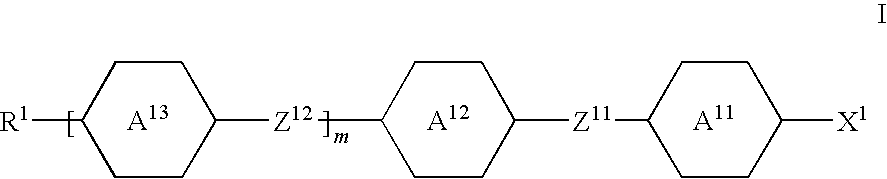
Electro-optical light control element, electro-optical display and control medium
a technology of electrooptical display and control medium, applied in thin material processing, instruments, chemistry apparatus and processes, etc., can solve the problems of dielectrically positive liquid crystals having worse transmission than dielectrically negative liquid crystals, and achieve short response times, favourable effect on response times, and influence the response time of ffs light-modulation elements
- Summary
- Abstract
- Description
- Claims
- Application Information
AI Technical Summary
Benefits of technology
Problems solved by technology
Method used
Image


Examples
example 1
[0198]A liquid-crystal mixture of the following composition is prepared and investigated.
CompositionCompoundConcentrationNo.Abbreviation / % by weight1CCP-3-OT3.02CCG-V-F5.03CCQU-5-F8.04PGU-3-F8.55PUQU-2-F7.56PUQU-3-F7.07CCGU-3-F2.58CC-3-V116.09CC-5-V16.010PP-1-2V18.511CCP-V-114.012CCP-V2-14.0Σ100.0Physical propertiesT(N, I) =79.0°C.ne(20° C., 589 nm) = 1.5970Δn(20° C., 589 nm) = 0.1095ε||(20° C., 1 kHz) =10.1 Δε(20° C., 1 kHz) =+7.0 K120° C.) =14.7pNK2(20° C.) =5.9pNK3(20° C.) =14.5pNK1 / K2(20° C.) =2.46K1 / K3(20° C.) =1.00K3 / K2(20° C.) =2.46γ1(20° C.) =72mPa · sTN:V0(20° C.) =1.52V
[0199]An electro-optical test cell with a light-switching element containing the liquid-crystal mixture is produced as described in Comparative Example 1. The layer thickness of the modulation medium is 3.6 μm and the optical retardation is thus 0.39 μm.
[0200]The test cell is investigated as described in the Comparative Example.
[0201]The value of the threshold voltage (V10) is 1.99 V, the value of the mid-gr...
example 2
[0204]A liquid-crystal mixture of the following composition is prepared and investigated as described under Example 1.
CompositionCompoundConcentration / No.Abbreviation% by weight1CCP-2-OT5.02CCP-3-OT5.03CCP-5-OT1.54PGU-3-F5.05PUQU-3-F13.06CC-3-V20.07CC-3-V111.58CC-5-V10.09PP-1-2V18.510CCP-V-111.011CCP-V2-16.012CPP-3-24.0Σ100.0Physical propertiesT(N, I) =75.0°C.ne(20° C., 589 nm) =1.5875Δn(20° C., 589 nm) =0.1011ε||(20° C., 1 kHz) =14.5Δε(20° C., 1 kHz) =+7.1K120° C.) =14.5pNK2(20° C.) =6.1pNK3(20° C.) =14.8pNK1 / K2(20° C.) =2.37K1 / K3(20° C.) =0.98K3 / K2(20° C.) =2.43γ1(20° C.) =50mPa · sTN:V0(20° C.) =1.88V
[0205]The corresponding test cell is investigated as described in the Comparative Example. Comparably good results are achieved.
example 3
[0206]A liquid-crystal mixture of the following composition is prepared and investigated as described under Example 1.
CompositionCompoundConcentration / No.Abbreviation% by weight1CCP-3-OT8.02CCP-4-OT8.03CCP-5-OT10.04PGU-2-F4.05CCQU-3-F10.06PUQU-3-F20.07CC-3-V10.08CC-3-V111.09CCP-V-14.010PP-1-2V111.011CPP-3-24.0Σ100.0Physical propertiesT(N, I) =77.0°C.ne(20° C., 589 nm) =1.5934Δn(20° C., 589 nm) =0.1011ε||(20° C.,1 kHz) =12.3Δε(20° C., 1 kHz) =+9.1K120° C.) =15.9pNK2(20° C.) =7.5pNK3(20° C.) =14.0pNK1 / K2(20° C.) =2.12K1 / K3(20° C.) =1.14K3 / K2(20° C.) =12873γ1(20° C.) =77mPa · sTN:V0(20° C.) =1.39V
[0207]The corresponding test cell is investigated as described in the Comparative Example and comparably good results are achieved.
PUM
 Abstract
Description
Claims
Application Information