Battery module of compact joint structure

a battery module and compact technology, applied in the field of batteries, can solve the problems of increasing the total size of the system, low manufacturing cost of pouch-shaped batteries, and complex assembly process of the battery body, and achieve the effect of limited installation spa

Active Publication Date: 2010-07-29
LG ENERGY SOLUTION LTD
View PDF1 Cites 10 Cited by
  • Summary
  • Abstract
  • Description
  • Claims
  • Application Information

AI Technical Summary

Benefits of technology

[0010]Specifically, it is an object of the present invention to provide a battery module that can be easily and stably mounted to a predetermined position of a vehicle, such that the structure of the joint structure of the battery module is not exposed to the outside, whereby the coupling of the battery module to the vehicle is easily and stably accomplished.
[0026]The middle- or large-sized battery system according to the present invention may be manufactured by combining the battery modules based on a desired power and capacity. The middle- or large-sized battery system is previously used in electric vehicles, hybrid electric vehicles, electric motorcycles, or electric bicycles, which have a limited installation space and are exposed to frequent vibrations and strong impacts, in consideration of the installation efficiency and structural stability of the battery system.

Problems solved by technology

Especially, much interest is currently generated in the pouch-shaped battery, which uses an aluminum laminate sheet as a sheathing member, because the weight of the pouch-shaped battery is small and the manufacturing costs of the pouch-shaped battery are low.
However, when a middle- or large-sized battery module is constructed using a plurality of battery cells or a plurality of unit modules each of which includes a predetermined number of battery cells, a plurality of members are generally needed to mount the battery cells or the unit modules in a middle- or large-sized battery module case and to mechanically couple the middle- or large-sized battery module case to a mounting member, such as a body frame, of a vehicle, and, as a result, a process for assembling the members is very complicated.
Furthermore, there is needed a space for coupling the members, with the result that the total size of the system is increased.
However, the above-described technology has a problem in that the joint structure is formed only at one side of the battery frame, with the result that the batteries are spaced apart from the battery frame, and therefore, when impacts, such as vibrations, are applied to joint structure from the vehicle, the joint structure is not structurally stable.
Also, the above-described technology has a problem in that the joint structure includes a plurality of joint members, with the result that the manufacturing costs are increased, and the assembly process to mount the battery frame to the floor panel of the vehicle is not easily performed.

Method used


Image

  • Battery module of compact joint structure
  • Battery module of compact joint structure
  • Battery module of compact joint structure

Examples


Embodiment Construction

[0031]Now, preferred embodiments of the present invention will be described in detail with reference to the accompanying drawings. It should be noted, however, that the scope of the present invention is not limited by the illustrated embodiments.

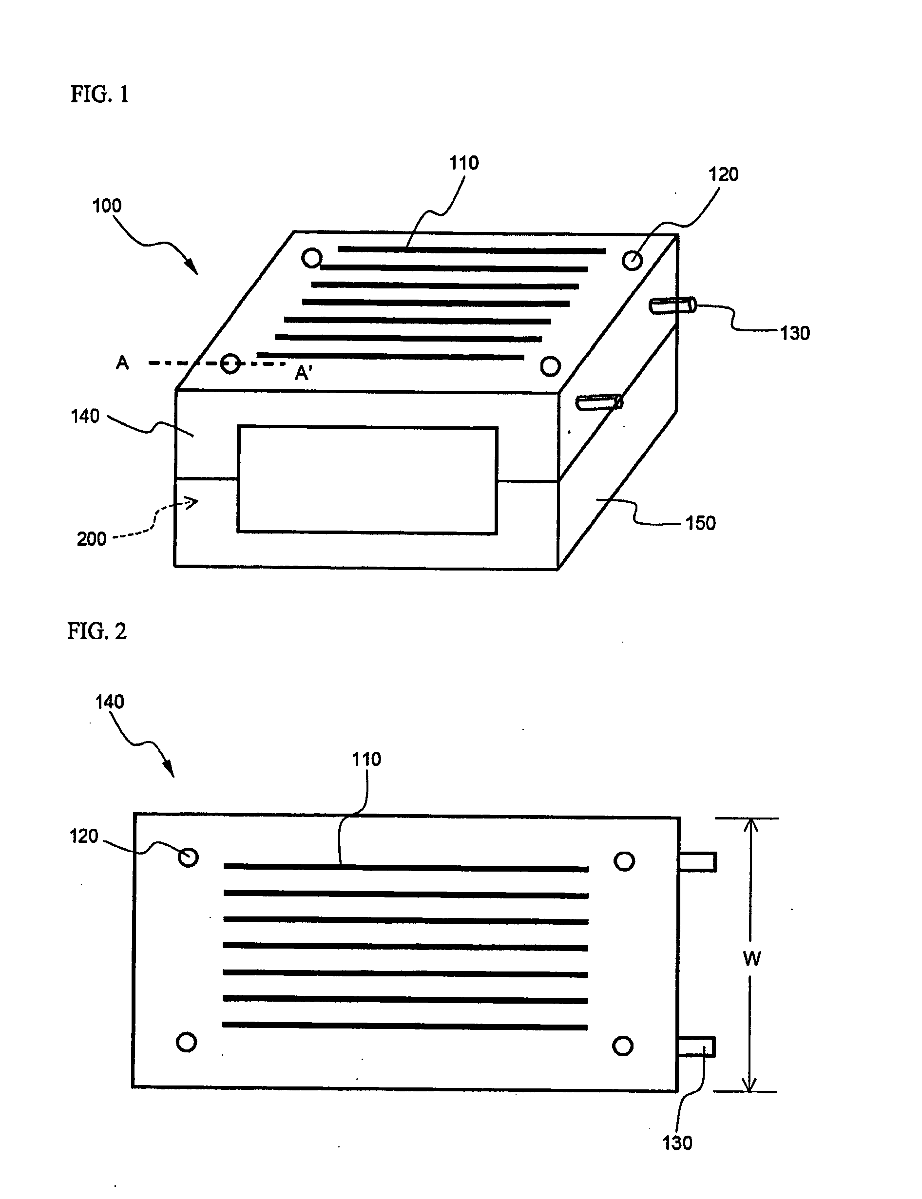
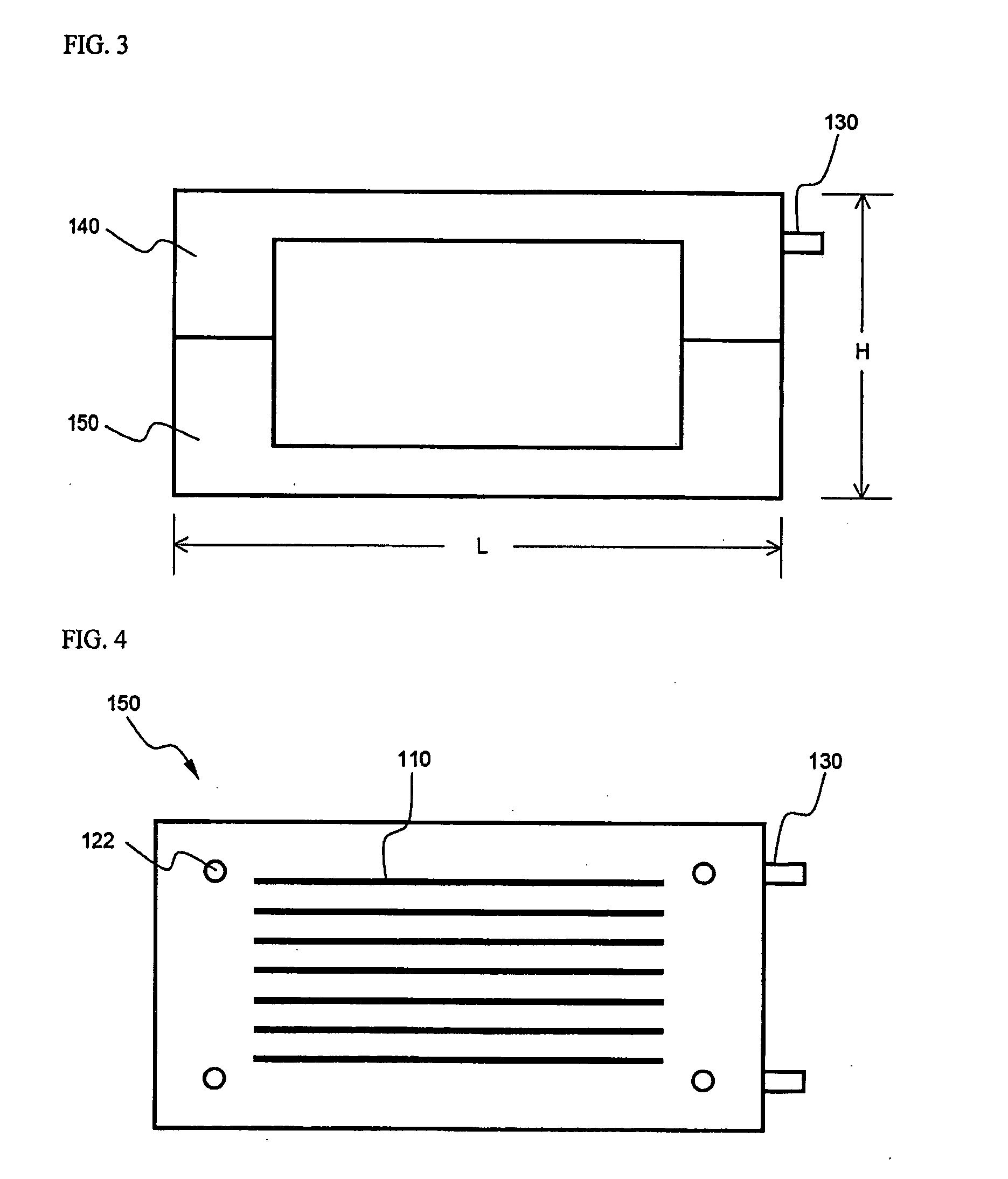
[0032]FIG. 1 is a perspective view typically illustrating a battery module according to a preferred embodiment of the present invention, and FIGS. 2 to 4 are a plan view, a front view, and a bottom view typically illustrating the battery module, respectively.

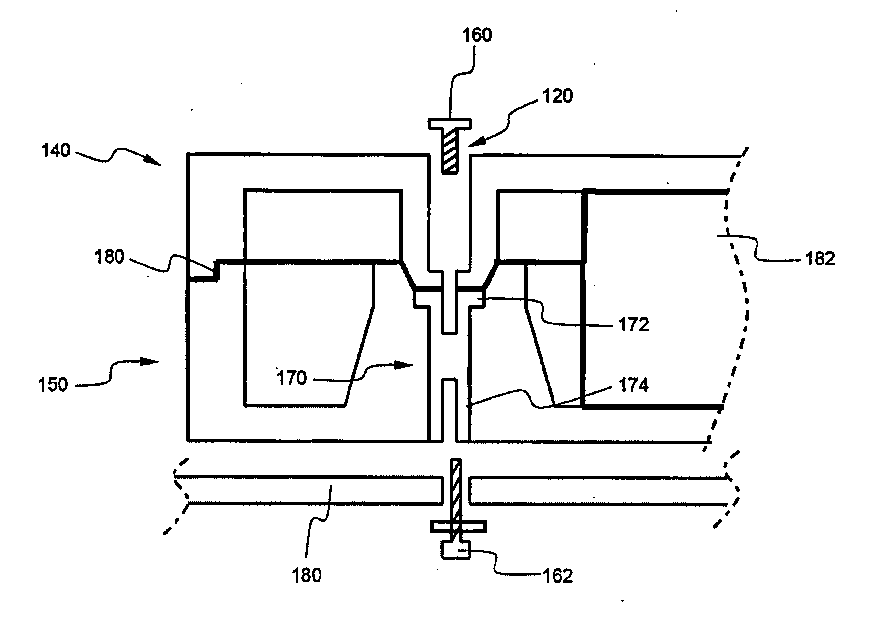
[0033]Referring to these drawings, the battery module 100 includes a plurality of battery cells or unit modules 200, an upper module case 140 and a lower module case 150, between which the battery cells or the unit modules 200 are mounted, and upper joint though-holes 120 and lower joint through-holes 122.

[0034]Electrode terminals 130 protrude from one side of the upper module case 140. The upper module case 140 is provided at the top thereof with a plurality of slits 110, which extend i...


PUM

PropertyMeasurementUnit
diameteraaaaaaaaaa
strengthaaaaaaaaaa
sizeaaaaaaaaaa

Abstract

Disclosed herein is a battery module including a charge and discharge stack, constituted by a plurality of secondary battery cells that can be charged and discharged or a plurality of unit modules having the secondary battery cells, mounted between an upper module case and a lower module case, wherein the lower module case is provided with joint structures including coupling parts (upper and lower coupling parts) for allowing both upward and downward couplings, and the upper module case is provided with joint holes communicating with the upper coupling parts of the joint structures. The battery module according to the present invention has the effect of reinforcing the low mechanical strength of the battery cells while the weight and size of the battery module is minimized. Also, the battery module according to the present invention is mounted to an inner frame of a vehicle or an additional frame fixed in the vehicle by a simple joint structure without using a plurality of members for a mechanical joint, whereby the manufacturing costs of the battery module are generally decreased. Furthermore, the battery module according to the present invention is safely protected when vibrations are generated from the vehicle during the driving of the vehicle. In addition, it is possible to easily manufacture a middle- or large-sized battery system having desired power and capacity using the battery module as a unit body.

Description

FIELD OF THE INVENTION[0001]The present invention relates to a battery module, and, more particularly, to a battery module including a charge and discharge stack, constituted by a plurality of secondary battery cells that can be charged and discharged or a plurality of unit modules having the secondary battery cells, mounted between an upper module case and a lower module case, wherein the lower module case is provided with joint structures including coupling parts (upper and lower coupling parts) for allowing both upward and downward couplings, and the upper module case is provided with joint holes communicating with the upper coupling parts of the joint structures.BACKGROUND OF THE INVENTION[0002]Recently, a secondary battery, which can be charged and discharged, has been widely used as an energy source for wireless mobile devices. Also, the secondary battery has attracted considerable attention as a power source for electric vehicles (EV) and hybrid electric vehicles (HEV), which...

Claims


Application Information

Patent Timeline
Patent Type & Authority Applications(United States)
IPC IPC(8): H01M2/24H01M50/529H01M50/20H01M50/204H01M50/262H01M50/296
CPCH01M2/1083H01M10/46H01M10/0413H01M6/42Y02E60/10H01M50/20H01M50/204H01M50/296H01M50/262
Inventor YANG, JAE HUNYANG, HEEKOOKYOON, JONGMOON
Owner LG ENERGY SOLUTION LTD
Why Eureka
Try Eureka