Manufacturing method of airtight container and image displaying apparatus

Inactive Publication Date: 2010-07-29
CANON KK
View PDF10 Cites 9 Cited by
  • Summary
  • Abstract
  • Description
  • Claims
  • Application Information

AI Technical Summary

Benefits of technology

[0009]The present invention aims, in a manufacturing method of an airtight container including a process of sealing a through-hole by a cover member, to provide the manufacturing method which can secure sealing performance and also

Problems solved by technology

This is because, although it is necessary to heat and then soften or melt the sealant to uniformly arrange and form it around the through-hole, there is a fear at this time that the sealant flows into the through-hole due to a difference between internal and external pressures of the container.
Thus, since the cap is in tightly contact with the through-hole easily, it becomes difficult for the sealant t

Method used


Image

  • Manufacturing method of airtight container and image displaying apparatus
  • Manufacturing method of airtight container and image displaying apparatus
  • Manufacturing method of airtight container and image displaying apparatus

Examples


first embodiment

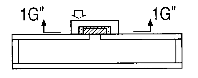
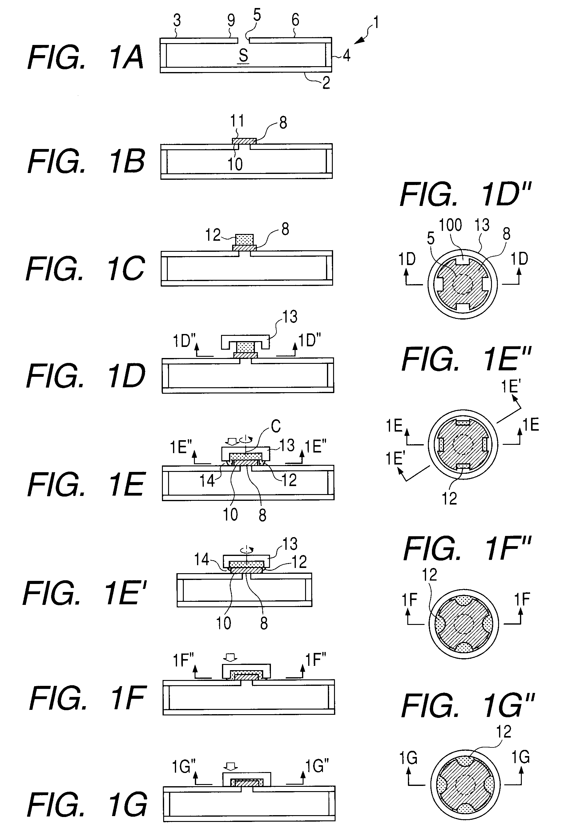
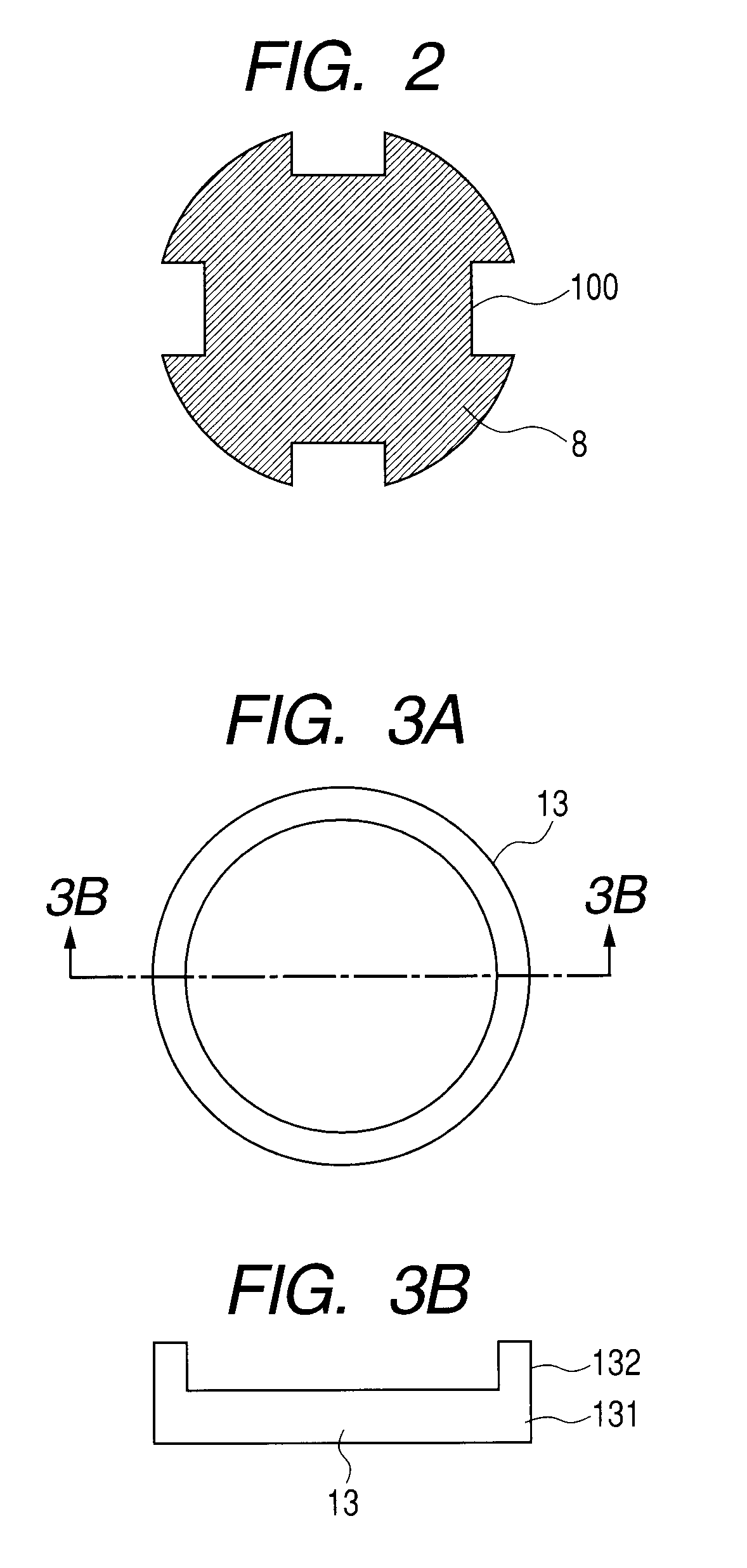
[0030]The first embodiment of the present invention will be described with reference to FIGS. 1A to 1G″. Here, FIGS. 1A to 1G″ are the schematic step views indicating a sealing process, which can be particularly preferably used in a case where a through-hole is sealed under a state that the through-hole of an airtight container is placed on the upper surface of an envelope. Incidentally, FIGS. 1D″, 1E″, 1F″, and 1G″ are the cross sectional views (i.e., views toward upward) respectively along the 1D″-1D″ line in FIG. 1D, the 1E″-1E″ line in FIG. 1E, the 1F″-1F″ line in FIG. 1F, and the 1G″-1G″ line in FIG. 1G. Further, FIGS. 1D, 1E, 1F, and 1G are the cross sectional views respectively along the 1D-1D line in FIG. 1D″, the 1E-1E line in FIG. 1E″, the 1F-1F line in FIG. 1F″, and the 1G-1G line in FIG. 1G″. Furthermore, FIG. 1E′ is the cross sectional view along the 1E′-1E′ line in FIG. 1E″.

[0031](Step S1)

[0032]Initially, an inside S of a container 1 is exhausted via a through-hole 5 p...

second embodiment

[0048]The present embodiment is different from the first embodiment in a point that a through-hole is sealed by bringing a laminated body composed of a plate member, a sealant and a cover member into contact with the through-hole from the downside of the through-hole. Also, the present embodiment is different from the first embodiment in a point that grooves are formed not on the plate member but on the cover member, and other points in the present embodiment are the same as those in the first embodiment. Therefore, in the following description, the points different from the first embodiment will be mainly described. Namely, as to the matters not described in the following, the description in the first embodiment should be referred.

[0049]The second embodiment of the present invention will be described with reference to FIGS. 5A to 5E″. Here, FIGS. 5A to 5E″ are the schematic step views indicating a sealing process which can be especially preferably used in a case where the through-h...

example 1

[0062]This is an example of manufacturing an airtight container by using the first embodiment illustrated in FIG. 1. Hereinafter, this example will be described with reference to FIG. 7.

[0063]In this example, the container 1 was stored in a vacuum-exhaust chamber 31, and the vacuum-exhaust chamber 31 was then exhausted to be vacuumized by using an exhaust unit 22 containing a turbo molecular pump and a dry scroll pump. Further, heaters 19a and 19b used as heating units were provided in the vacuum-exhaust chamber 31, and the throughhole 5 having the diameter of 3 mm was provided on the upper surface of the container 1.

[0064]FIGS. 8A and 8B are views of the plate member 8 and the cover member 13. More specifically, FIG. 8A is the plan view of the plate member and the cover member, and FIG. 8B is the cross sectional view along the 8B-8B line in FIG. 8A.

[0065]As the plate member 8, soda lime glass having the diameter of 5 mm and the thickness of 0.3 μm was prepared. The four grooves 100...


PUM

PropertyMeasurementUnit
Thicknessaaaaaaaaaa
Diameteraaaaaaaaaa
Electrical conductoraaaaaaaaaa

Abstract

In an airtight container manufacturing method including sealing a through-hole by a cover, it secures sealing performance and restrains a sealant from flowing into the through-hole. The method comprises: (a) exhausting the inside of a container through the through-hole provided on the container; (b) arranging a plate member having, at its periphery, grooves penetrating the plate member in its plate thickness direction on the outer surface of the container the inside of which has been exhausted, so as to close up the through-hole; and (c) arranging the cover so as to cover the plate member via the sealant and bonding the cover and the outer surface of the container via the sealant, wherein the sealing includes hardening the sealant after deforming the sealant as pressing the plate member by the cover so that the sealant is positioned between the cover and the outer surface of the container via the grooves.

Description

BACKGROUND OF THE INVENTION[0001]1. Field of the Invention[0002]The present invention relates to a manufacturing method of an airtight container. In particular, the present invention relates to a manufacturing method of a vacuum airtight container (envelope) used for a flat panel image displaying apparatus.[0003]2. Description of the Related Art[0004]An image displaying apparatus, in which a number of electron-emitting devices for emitting electrons according to image signals are provided on a rear plate and a fluorescent film for displaying an image by emitting light in response to irradiation of electrons is provided on a face plate, and of which the inside is maintained with a vacuum, has been known. In the image displaying apparatus like this, generally, the face plate and the rear plate are bonded to each other through a support frame, thereby forming an envelope. In case of manufacturing the image displaying apparatus like this, it is necessary to exhaust the inside of the env...

Claims


Application Information

Patent Timeline
IPC IPC(8): H01J9/26B23P11/00
CPCH01J9/261H01J9/40Y10T29/49826H01J2209/26H01J2329/94H01J29/86
Inventor KAMIGUCHI, KINYANAKAZAWA, TOMONORIKAWASE, TOSHIMITSUITO, NOBUHIROHASEGAWA, MITSUTOSHINAKANISHI, KOICHIROKOYANAGI, KAZUO
Owner CANON KK
Why Eureka
Try Eureka