
Method For Multi-Scale Geomechanical Model Analysis By Computer Simulation

a geomechanical model and computer simulation technology, applied in the field of geomechanical modeling, can solve problems such as stress in formation, damage to the completion assembly of the well, and subsidence of the earth at the surface of the earth

Inactive Publication Date: 2010-07-29
EXXONMOBIL UPSTREAM RES CO
View PDF95 Cites 93 Cited by
  • Summary
  • Abstract
  • Description
  • Claims
  • Application Information

AI Technical Summary

Benefits of technology

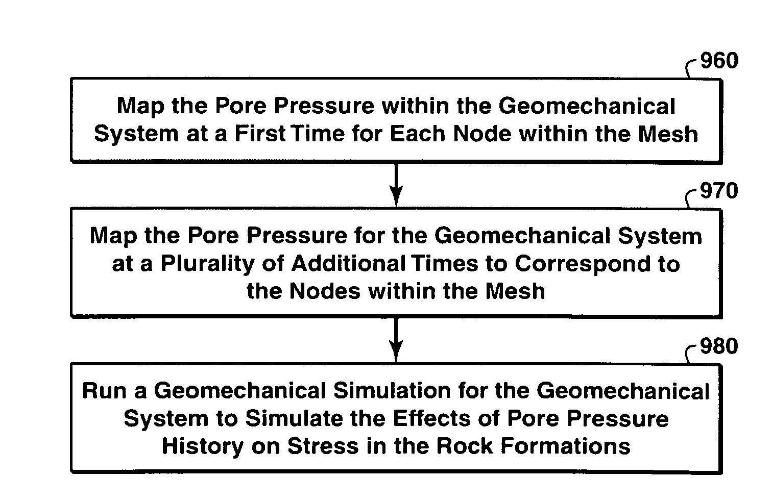
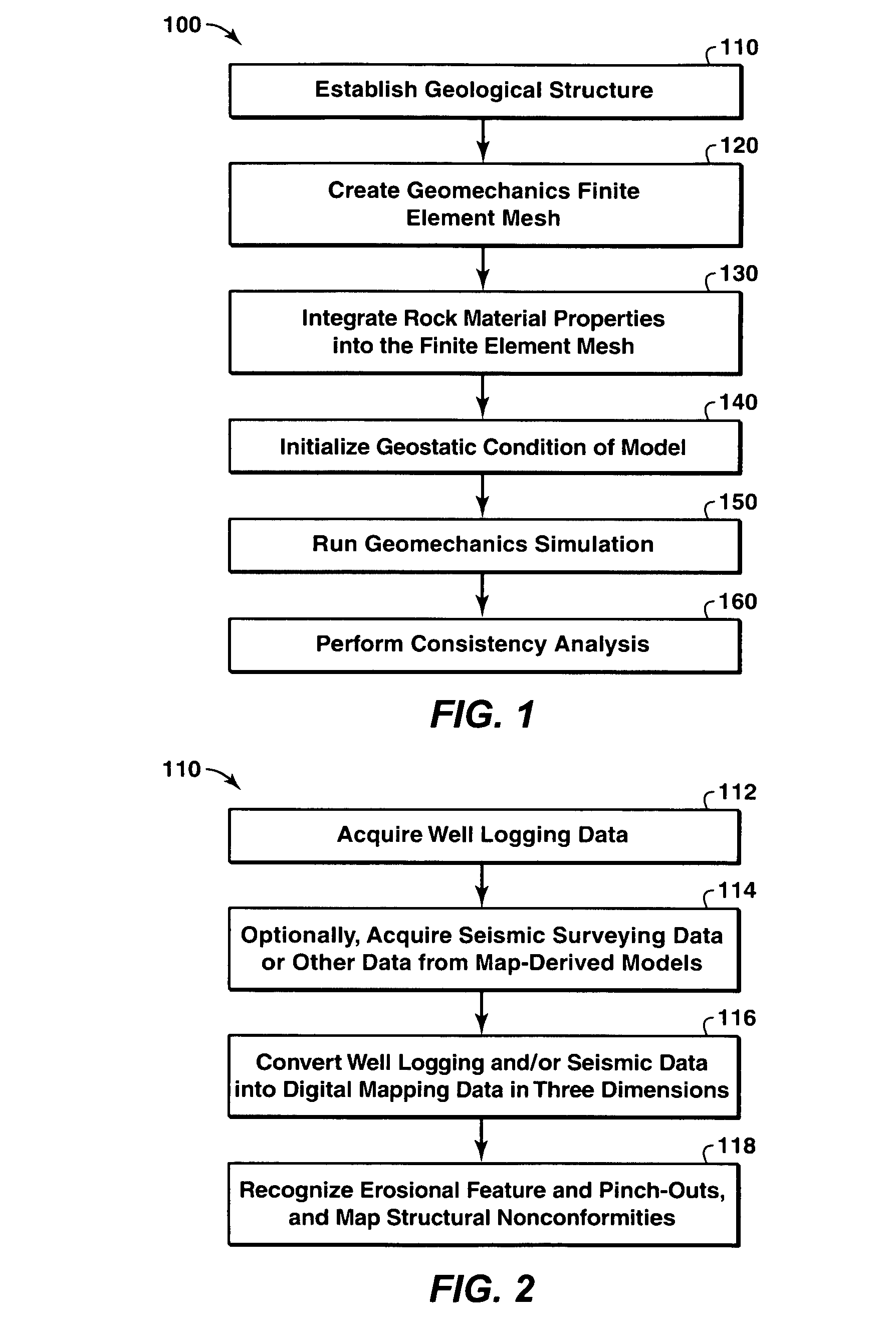
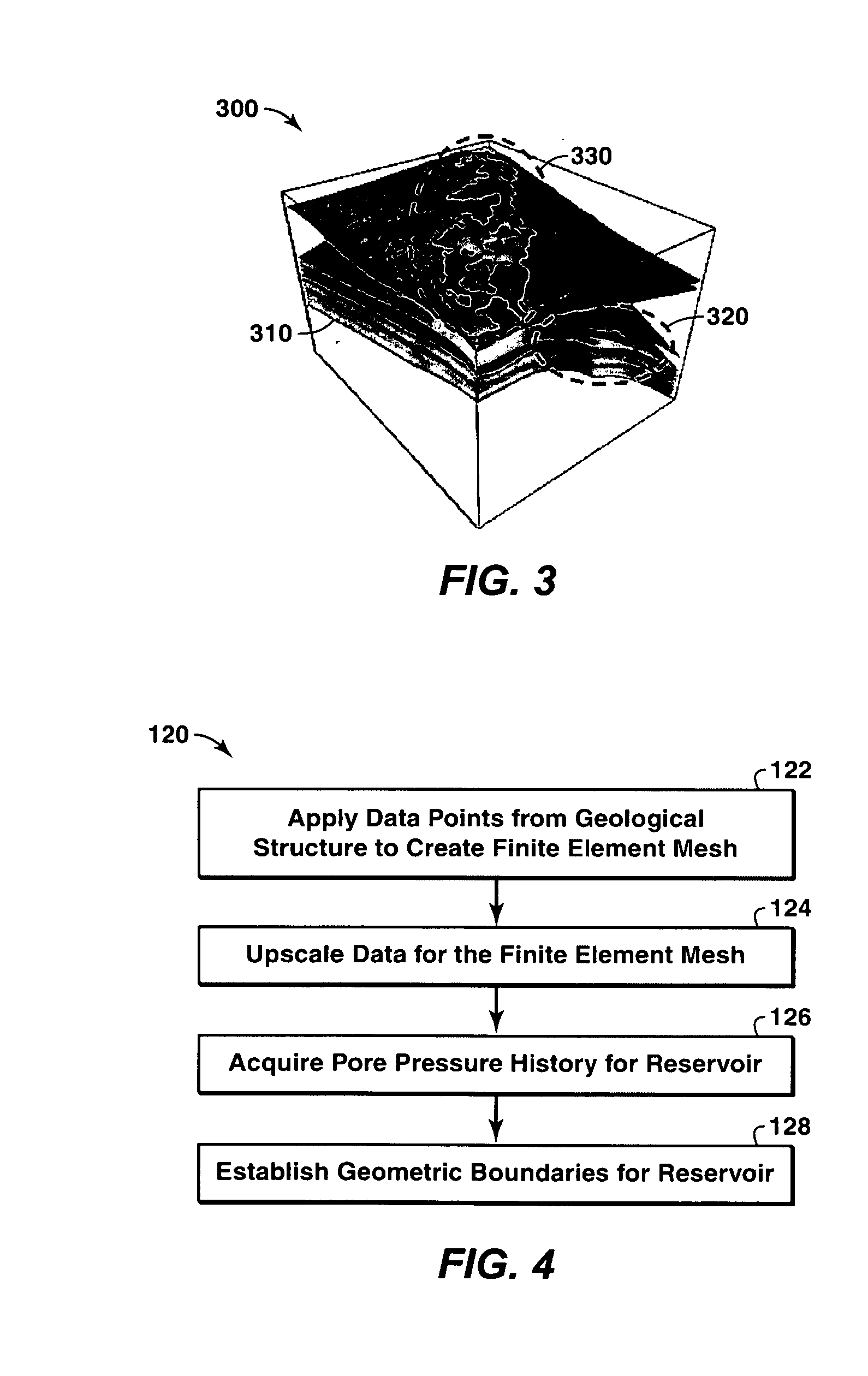
The patent text describes a method for automatically modeling a geomechanical system, such as a hydrocarbon reservoir, using computer software. The method involves creating a map-based geological model of the system by using well logging data and seismic data. This model is then used to create a finite element-based global geomechanical model, which is a three-dimensional representation of the system. The method also includes running a geomechanics simulation to determine changes in stress caused by changes in pore pressure. The technical effects of this patent text include automating the modeling process, improving the accuracy of the model, and increasing the efficiency of the simulation process.

Problems solved by technology

When the state of stress within and above the hydrocarbon-bearing reservoir exceeds the mechanical limits of wells completed in the production area, the completion assemblies forming the wells may be damaged.
This, in turn, can cause a subsidence of the earth at the surface.
This, in turn, can create stresses in the formation that may affect wellbore casings.
Further, increased pore pressure may cause heave at the surface of the earth.
Subsidence particularly has the potential of damaging production wells formed in a production area.
In this respect, downward earth movement can create damaging hoop and compressional stresses on wellbore casings, cement jobs, and downhole equipment.

Method used


Image

  • Method For Multi-Scale Geomechanical Model Analysis By Computer Simulation
  • Method For Multi-Scale Geomechanical Model Analysis By Computer Simulation
  • Method For Multi-Scale Geomechanical Model Analysis By Computer Simulation

Examples


Embodiment Construction

Definitions

[0042]As used herein, the term “burial” refers to a geologic process, whether continuous or discontinuous, and whether related to sedimentary deposition, volcanic eruption and / or other geologic process wherein multiple strata are placed in a substantially successive manner, one stratum atop another, in a corresponding series of stratum-producing phases leading to a formation's creation. As used herein, where the term “burial” is associated with a rock property value (e.g., Poisson's Ratio or Young's Modulus) for a stratum of interest, the term designates a virtual value of the rock property for each stratum considered pertinent to developing a stratigraphic model suitable for performing the desired stress analysis of the formation. Depending on the formation, the oldest stratum and the successively newer strata of interest can be produced in any one of the primary geologic eras.

[0043]“Lithology” means a description of the physical and approximate compositional character o...


PUM


Abstract

A method of predicting earth stresses in response to changes in a hydrocarbon-bearing reservoir within a geomechanical system includes establishing physical boundaries for the geomechanical system, acquiring logging data from wells drilled, and acquiring seismic data for one or more rock layers. The well and seismic data are automatically converted into a three-dimensional digital representation of one or more rock layers within the geomechanical system, thereby creating data points defining a three-dimensional geological structure. The method also includes (a) applying the data points from the geological structure to derive a finite element-based geomechanical model, and (b) initializing a geostatic condition in the geomechanical model, and then running a geomechanics simulation in order to determine changes in earth stresses associated with changes in pore pressure or other reservoir characteristics within the one or more rock layers.

Description

CROSS REFERENCE TO RELATED APPLICATIONS[0001]This application claims the benefit of U.S. Provisional Application No. 60 / 966,031, filed 24 Aug. 2007.BACKGROUND OF THE INVENTION[0002]1. Field of the Invention[0003]The present invention relates to the field of geomechanical modeling. More specifically, the present invention relates to the analysis of earth stresses associated with hydrocarbon recovery processes.[0004]2. Background of the Invention[0005]A subterranean hydrocarbon-bearing reservoir is confined by a state of in-situ tectonic stress. When producing hydrocarbons from the reservoir, the stress state of the reservoir may change. When the state of stress within and above the hydrocarbon-bearing reservoir exceeds the mechanical limits of wells completed in the production area, the completion assemblies forming the wells may be damaged.[0006]A concern may also exist with respect to the effect that fluid removal from the reservoir may have at the earth surface. In this respect, i...

Claims


Application Information

Patent Timeline
Patent Type & Authority Applications(United States)
IPC IPC(8): G06G7/50G06F17/50
CPCG01V11/00E21B49/006
Inventor HSU, SHENG-YUANPAKAL, RAHULSEARLES, KEVIN H.DUFFY, BRIAN W.
Owner EXXONMOBIL UPSTREAM RES CO
Learn More