Sniper Pole Shear

Inactive Publication Date: 2010-08-05
ARCHMAN DI PITTAU GIOVANNI & C
View PDF6 Cites 16 Cited by
  • Summary
  • Abstract
  • Description
  • Claims
  • Application Information

AI Technical Summary

Benefits of technology

[0016]Advantageous effects of the invention
[0017]simplified and reduced maintenance;
[0018]reduced conking-out ri

Problems solved by technology

The major disadvantages of the above said solutions are:
construction complexity and in particular, for the systems with cord and transmission sheave/s, the easy tangling of the cord tensioning between the sheaves, that generally are provided

Method used


Image

  • Sniper Pole Shear
  • Sniper Pole Shear
  • Sniper Pole Shear

Examples


Example

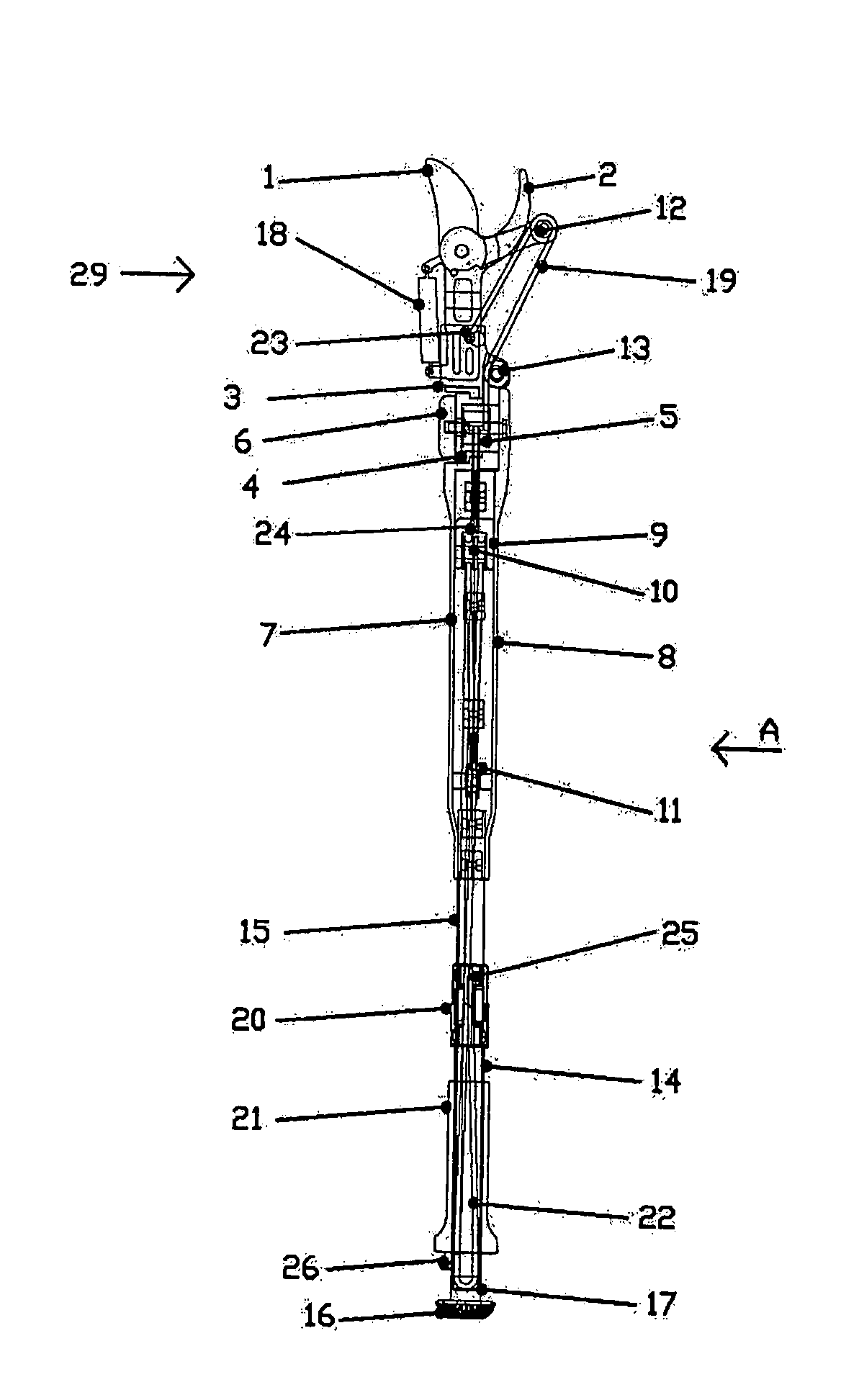
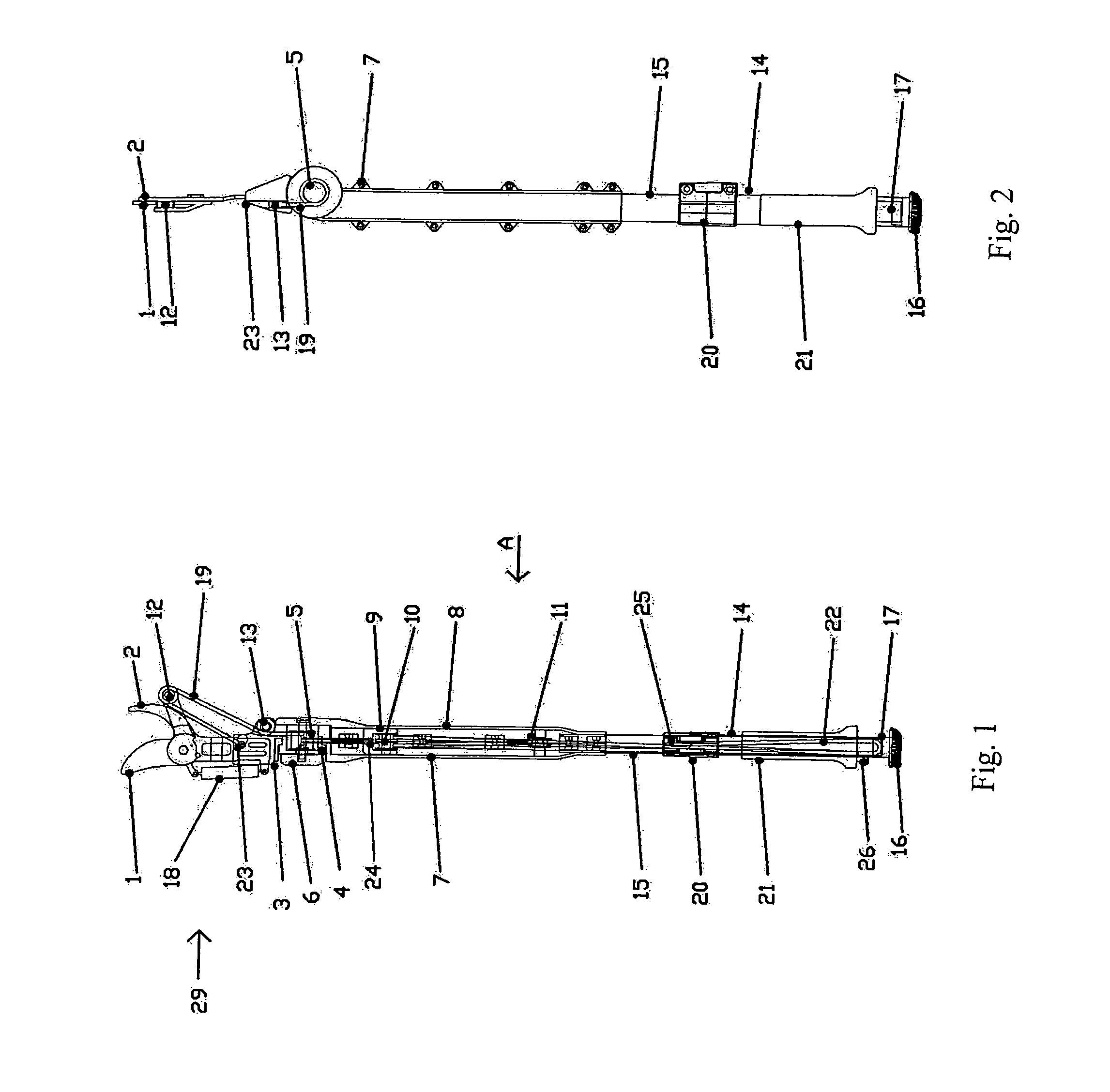
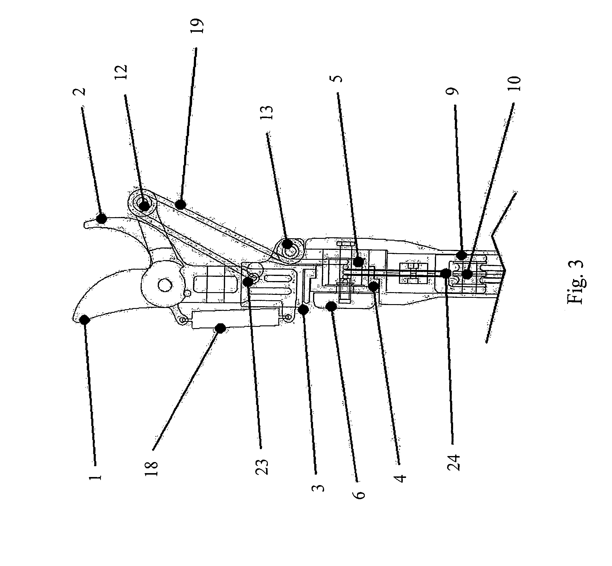
[0050]Referring to FIG. 5 the blade (1) is tapered with a convex with an acute angle sharp edge and is equipped with a slot (28) for the hooking of the return spring (18) and with an extension (27) for fixing the operating system that exploits the principle of the lever to realize the multiplication of the applied force during the cutting action.

[0051]Referring to FIG. 6 the counter-blade (2) is shaped with a cutting angle less acute in respect to the angle of the blade (1) and such angle is toothed to avoid the sliding of the branch during the cutting phase of the same.

[0052]Referring to FIG. 1 the blade (1) is mounted on the counter-blade (2) in such a way as to be able to rotate around the fixing point and close towards said counter-blade in such a way that the cutting action occurs both for the pressure of the blade on the piece to be cut kept in position by the counter-blade and for the sliding of the cutting surface of said blade on said piece to be cut.

[0053]The opening of th...


PUM


Abstract

Cutting tool of the scissor type with pruning head with fixed counter-blade and movable blade operated by a transmission arm on which a cord acts, sliding on sheaves. Said pruner head being connected to a telescopic extension pole by means of two side shells characterised in that the transmission of the command occurs by means of sheaves forming a tackle housed within said shells, said telescopic pole consisting of two pipes, one of which re-entering inside the other one, provided with grooves, sliding cap, pipe-clamp and command handle constituting a path of the command cord such as to allow the telescopic lengthening of the pole maintaining said cord in tense condition and maintaining the position of the command handle fixed.

Description

CROSS-REFERENCE TO RELATED APPLICATIONS[0001]The present application is a continuation of pending International patent application PCT / EP2008 / 008080 filed on Sep. 24, 2008, which designates the United States and claims priority from Italian patent application number UD2007A000178 filed on Sep. 26, 2007, the content of which is incorporated herein by reference.FIELD OF THE INVENTION[0002]This invention generally relates to the application field of cutting tools and in particular to loppers for pruning.BACKGROUND OF THE INVENTION[0003]In the field of the realization of cutting tools the recourse to telescopic systems is well known, particularly with extendible pole provided with a shear at the end and with a traction system at the handle side, generally with cord or other remote driving mechanism that shuts the blade on the corresponding counter-blade to allow the cutting operation on pieces placed at a distance not easily accessible by the operator, for example as in case of the prun...

Claims


Application Information

Patent Timeline
IPC IPC(8): A01G3/025
CPCA01G3/0255
Inventor PITTAU, GIOVANNI
Owner ARCHMAN DI PITTAU GIOVANNI & C
Why Eureka
Try Eureka