Thin stone or brick veneer wall system and clips therefor

a thin stone or brick veneer and wall system technology, applied in the direction of vertical ducts, building components, covering/linings, etc., can solve the problems of veneer walls of great weight, high cost, and high labor intensity of masonry contractors, so as to prevent the clip from deflecting or collapsing, strengthen the clip, and add to the overall strength of the wall system

Inactive Publication Date: 2010-08-05
SHOULDICE DESIGNER STONE
View PDF4 Cites 67 Cited by
  • Summary
  • Abstract
  • Description
  • Claims
  • Application Information

AI Technical Summary

Benefits of technology

[0012]The wall system of the present invention advantageously provides a more versatile, secure and mechanically stronger veneer wall than has been previously realized in the art for thin stone or thin brick. Facing elements are easier and faster to install than in previous systems, and require less skilled labor thereby permitting general tradesman and even the average building owner to erect a thin stone or thin brick veneer wall.
[0026]A third embodiment of the first clip may be utilized in constructing a mortarless veneer curtain wall. The first clip in the third embodiment has one base flange with upwardly and downwardly depending flanges depending from one end of the base flange. Therefore, when the upper and lower facing elements are linked by the clip there is virtually no space at the joint between the facing elements. To accommodate the thickness of the base flange, a thin portion of the edges at the rear face of the facing elements may be ground to form a seat. The third embodiment of the first clip can provide consistent horizontal leveling with a standard spacing (e.g. 0.03125 inches). Stacking facing elements in such a mortarless veneer curtain wall can give a stacked-stone appearance. The edges at the front face of the facing elements may be beveled to make the joint look like a mortar joint. Similarly, mortarless joints can be formed between horizontally adjacent facing elements.

Problems solved by technology

Such construction requires a skilled masonry contractor and is very time consuming.
Further, since individual bricks, blocks or other stone products are relatively thick and heavy at full depth, such construction is also expensive and leads to veneer walls of great weight.
Such materials tend to be lighter in weight but lose aesthetic appeal since they do not look sufficiently like brick or natural stone.
In addition, such products are more costly and, in most cases, require a specific contractor to install them.
Such products have a more natural stone or brick appearance, however, finding ways to easily, inexpensively and quickly construct veneer walls using such thin stones or thin bricks has been problematic.
Such an adhered thin stone or thin brick system is inherently less secure since improper application of the adhesive can lead to stones or bricks separating from the wall, which is both a nuisance and a safety problem.
Further, the adhered thin stone or thin brick system has not, in the past, been used in conjunction with other wall elements such as drainage board and weather-resistant wrap, thus thin stone or thin brick products have been preponderantly used in commercial building applications.
Although useful in particular cases, such systems lack versatility and simplicity, requiring brackets or clips with complicated structures and / or several separate components.
Such brackets or clips are more difficult to secure to structural walls and / or require tedious and time-consuming alignment of panels.

Method used


Image

  • Thin stone or brick veneer wall system and clips therefor
  • Thin stone or brick veneer wall system and clips therefor
  • Thin stone or brick veneer wall system and clips therefor

Examples


Embodiment Construction

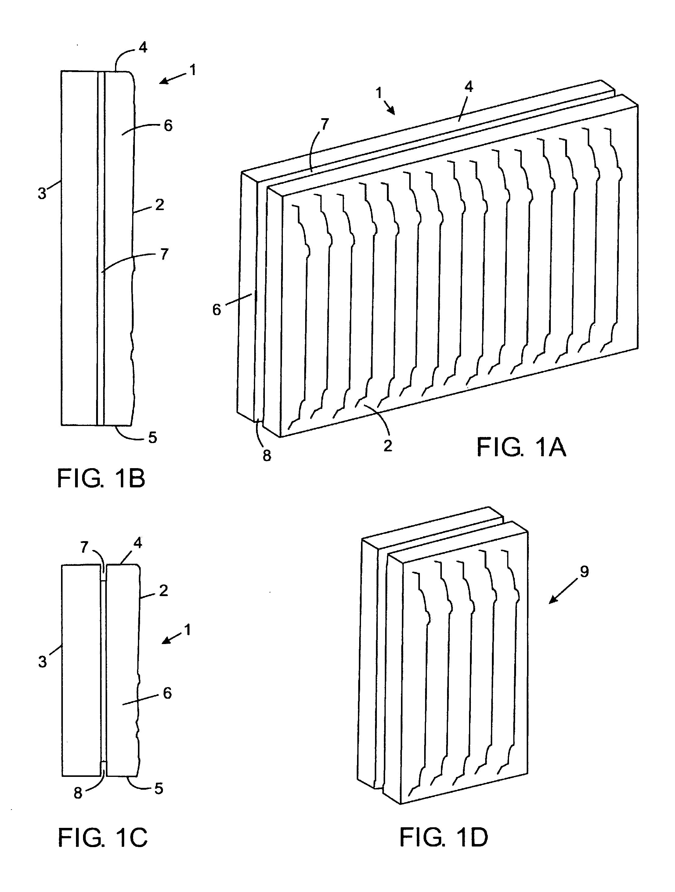
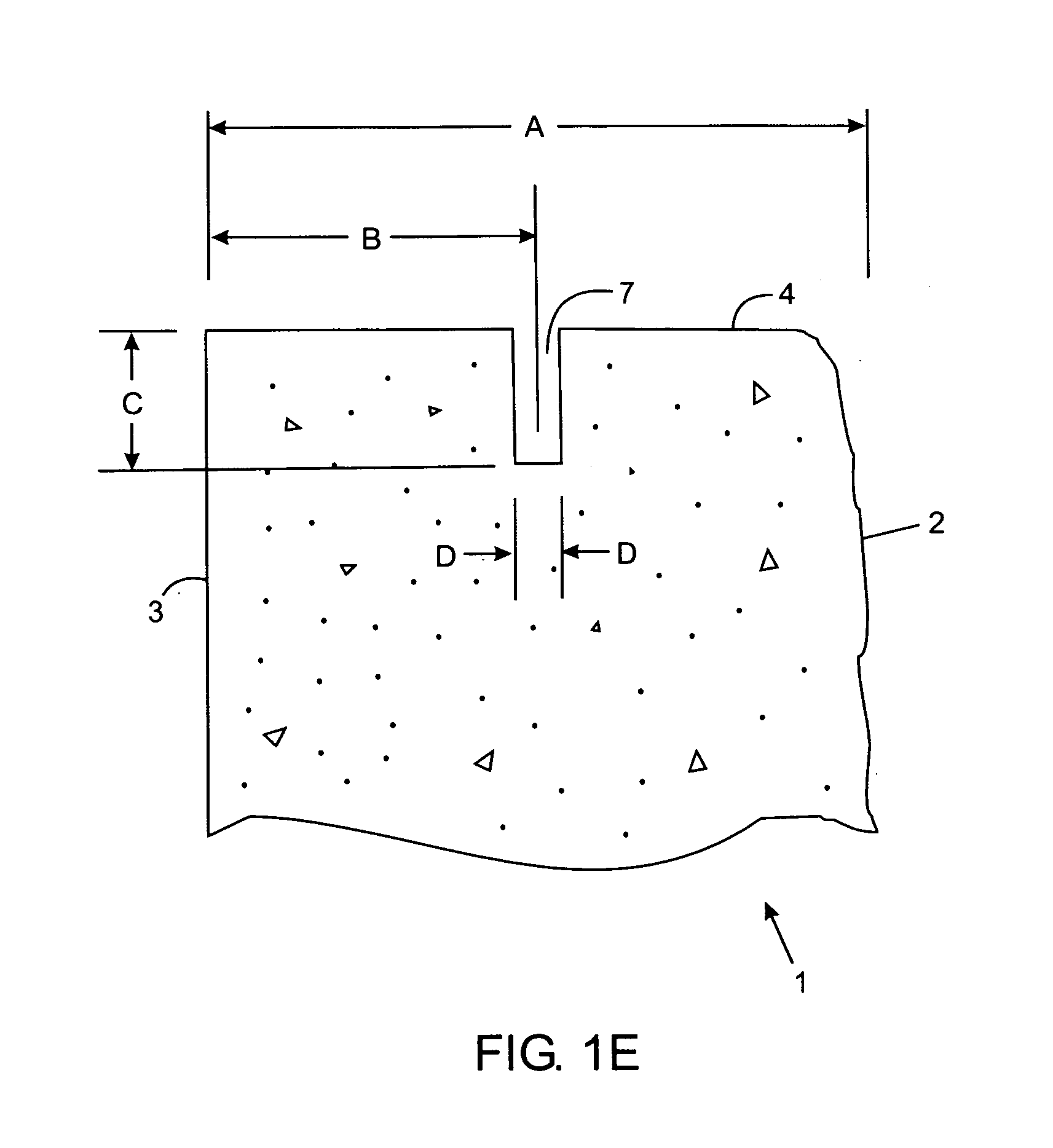
[0063]Referring to FIGS. 1A-1D, thin stone facing element 1 comprises front face 2, rear face 3, upper edge 4, lower edge 5 and two side edges 6. Groove 7 in the upper edge runs the entire length of the stone facing element from one side to the other side. Groove 8 in the lower edge runs the entire length of the stone facing element from one side to the other side. The front face of the stone facing element is dressed for aesthetic appeal since the front face presents outwardly when mounted in a veneer wall. Stone facing element 1 is 15.5 inches long by 7.5 inches in height. Stone facing element 9 depicted in FIG. 1D is the same as stone facing element 1 except that stone facing element 9 is only 5.0 inches long. Stone facing elements 1 and 9 may be used together in a thin stone veneer wall, and together with other sized stone facing elements if desired, to provide a more random appearance to the veneer wall.

[0064]Referring specifically to FIG. 1E, an enlarged portion of the side vi...


PUM


Abstract

A wall system, particularly for thin stone or thin brick veneer walls, has a plurality of stones or bricks with grooves running along the upper and lower edges and a plurality of clips for linking the stones or bricks. One type of clip having one or more connecting flanges links an upper stone or brick to a lower stone or brick with the one or more connecting flanges housed within the groove in the lower edge of the upper stone or brick and within the groove in the upper edge of the lower stone or brick. The one or more connecting flanges of the clip depend from one or more base flanges of the clip and have a width just equal to the distance from the rear face to the groove of the upper and lower stones or bricks. The one or more base flanges of the clip depend from a support flange of the clip. The support flange has one or more apertures for accepting a screw or nail for fastening the clip to a structural wall.

Description

CROSS-REFERENCE TO RELATED APPLICATIONS[0001]This application is a continuation of U.S. application Ser. No. 11 / 305,289 filed Dec. 19, 2005, which is incorporated herein by reference.FIELD OF THE INVENTION[0002]The present invention relates to thin stone or thin brick veneer wall systems and to clips for fastening facing elements thereof.BACKGROUND OF THE INVENTION[0003]Masonry veneer walls are typically constructed by laying bricks, blocks or other stone product in courses and mortaring the top of each course as the wall is being built from the bottom up. Conventionally, the lower course of bricks, blocks or other stone product is supported on a foundation (e.g. poured concrete) or an engineered angle iron to carry the mass load. Such construction requires a skilled masonry contractor and is very time consuming. Further, since individual bricks, blocks or other stone products are relatively thick and heavy at full depth, such construction is also expensive and leads to veneer walls...

Claims


Application Information

Patent Timeline
Patent Type & Authority Applications(United States)
IPC IPC(8): E04B2/32E04B2/34E04B1/70
CPCE04F13/14E04F13/0846
Inventor HUFF, ROBERTSHOULDICE, MARK
Owner SHOULDICE DESIGNER STONE
Why Eureka
Try Eureka