Micromechanical structures

a micromechanical structure and sensor technology, applied in the direction of acceleration measurement using interia force, turn-sensitive devices, instruments, etc., can solve the problems of electromechanical instability, sensing-mass elements will be pulled downward in the direction of the electrodes, and the frequency spread of the respective spring-mass system, so as to achieve the effect of increasing the absolute accuracy of setting the drive frequency and/or the detection frequency

Active Publication Date: 2010-08-05
ROBERT BOSCH GMBH
View PDF2 Cites 31 Cited by
  • Summary
  • Abstract
  • Description
  • Claims
  • Application Information

AI Technical Summary

Benefits of technology

[0005]A micromechanical structures of the present invention may have the advantage that interference effects on the drive frequency and / or detection frequency, both due to manufacturing-induced variations in the functional-layer thickness perpendicular to the main plane of extension and due to manufacturing-induced variations in the width of trench structures parallel to the main plane of extension, are reduced considerably. This is achieved by selecting a specific ratio between the width of the mass lines and the line width of the bending-spring elements. In this context, the width of the mass lines, as well as the line width of the bending-spring elements, in each case includes the effective width, i.e., the width of the mass lines after the micromechanical structure has been processed (particularly after the undercutting of the seismic mass). The average width of the mass lines lies between 20 and 50 percent, preferably between 25 and 40 percent, particularly preferably between 30 and 36, and extremely preferably, generally at 33 percent of the line width of the bending-spring elements. The absolute accuracy in setting the drive frequency and / or detection frequency is thereby markedly increased. The micromechanical structure preferably includes a micromechanical resonator or a micromechanical yaw-rate sensor.

Problems solved by technology

Production-induced variations in the trench widths of the spring lines and mass lines, hereinafter known as edge-loss spreads, disadvantageously lead to frequency spreads of the respective spring-mass system.
The conventional yaw-rate sensor has the further disadvantage that, because the sensing device in the form of electrodes is disposed on one side below the sensing-mass elements, there is the risk that the sensing-mass elements will be pulled downward in the direction of the electrodes in response to the application of a positive-feedback voltage and a quadrature-compensation voltage.
At very high voltage levels, this can even lead to electromechanical instability, what is termed “snapping”, in which the sensing-mass elements are pulled completely onto the electrodes.
However, in the case of the yaw-rate sensor, the suspension springs for securing the sensing-mass elements are mainly subject to bending stress in response to a displacement, the bending stiffness of the suspension springs increasing in proportion to the third power of the functional-layer thickness, while the mass increases only linearly with the functional-layer thickness.
For fully resonant operation of the yaw-rate sensor, it is therefore disadvantageous that a comparatively great frequency splitting must be set in order to compensate for manufacturing tolerances in the production of the yaw-rate sensor.

Method used


Image

  • Micromechanical structures
  • Micromechanical structures
  • Micromechanical structures

Examples


Embodiment Construction

[0030]Identical or corresponding parts are provided with the same reference numerals in the various figures, and are therefore generally in each case designated or mentioned only once, as well.

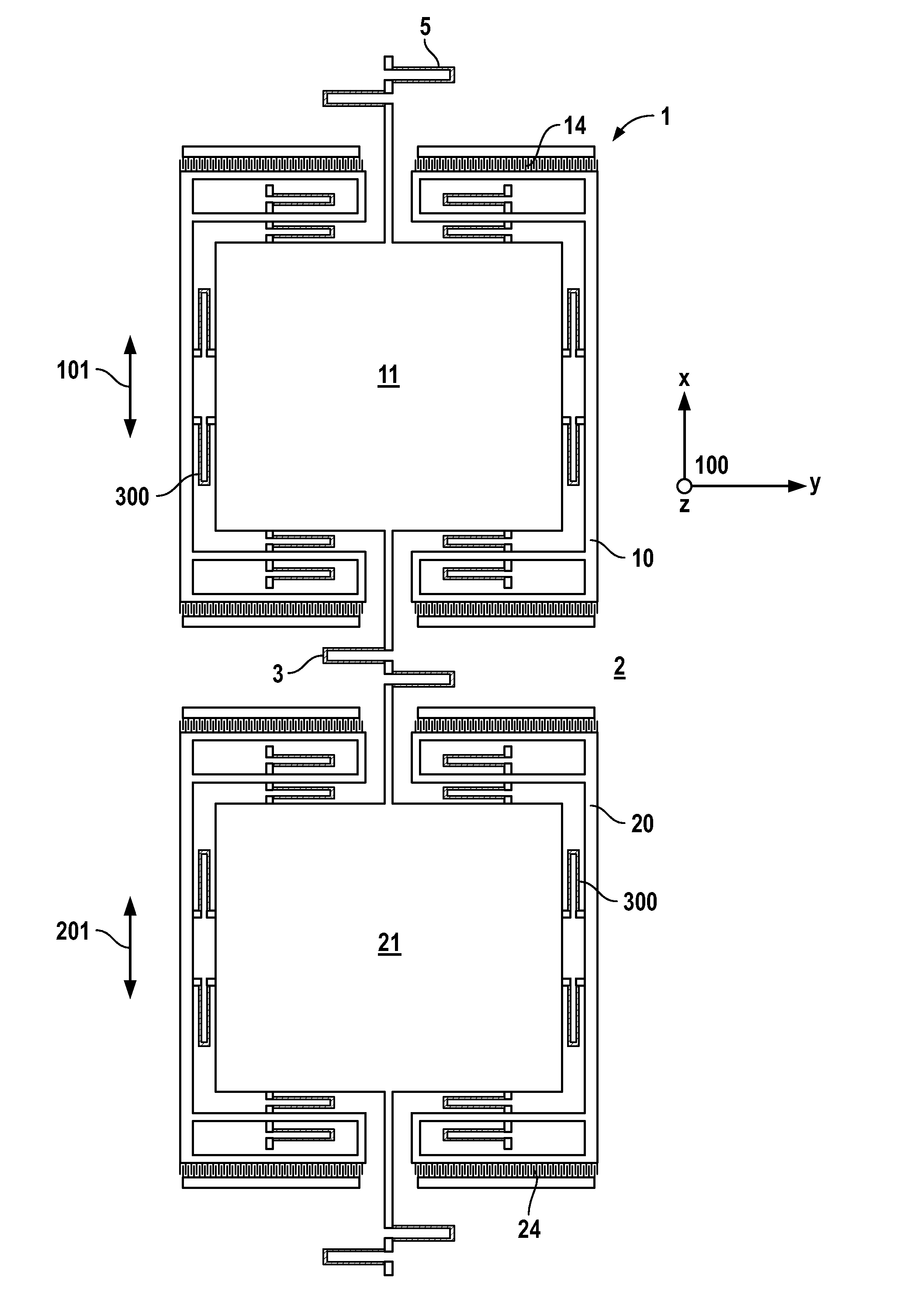
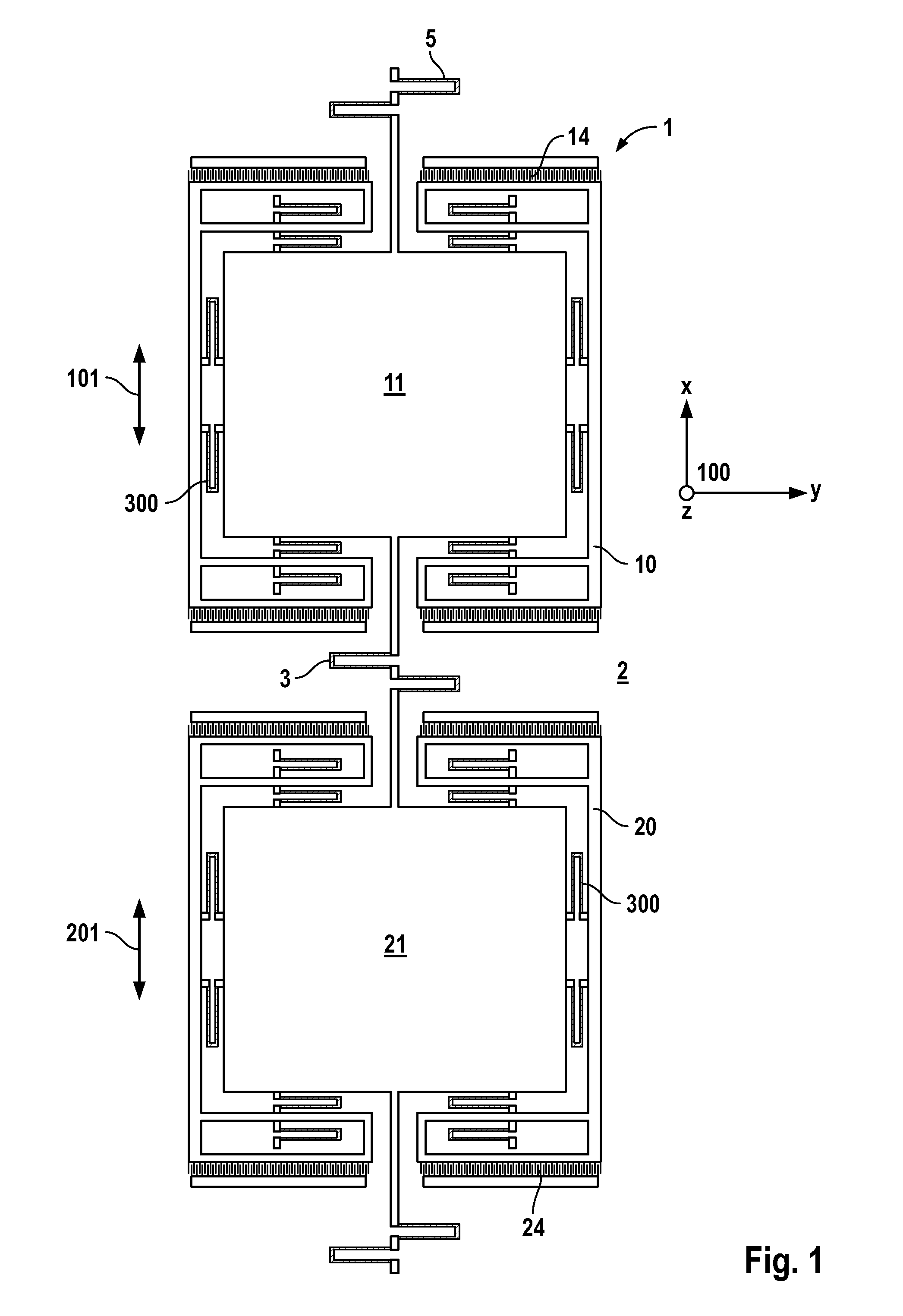
[0031]FIG. 1 shows a conventional yaw-rate sensor in the form of a micromechanical structure 1, the yaw-rate sensor having a substrate 2 with a main plane of extension 100. The yaw-rate sensor also includes a driving element 10 which is secured to substrate 2 with the aid of third coupling elements 4 in the form of further bending springs and which is excited by first comb drives 14 into a first oscillation 101 along a first direction X parallel to main plane of extension 100. A first sensing-mass element 11 is joined by further coupling means 300 to driving element 10 in a manner allowing movement. The yaw-rate sensor further has an identical second driving element 20 having a corresponding second sensing element 21 and second comb drives 24. First and second sensing-mass elements 11, 21 are ...


PUM


Abstract

A micromechanical structure including a substrate having a main plane of extension, and including a first seismic mass, the first seismic mass including a grid structure made of intersecting first mass lines and the first seismic mass being flexibly secured with the aid of first bending-spring elements, and moreover, a first line width of the first mass lines parallel to the main plane of extension being between 20 and 50 percent of a further first line width of the first bending-spring elements parallel to the main plane of extension.

Description

CROSS-REFERENCE[0001]The present application claims the benefit under 35 U.S.C. §119 of German Patent Application No. 102009000606.0 filed Feb. 4, 2009, which is expressly incorporated herein by reference in its entirety.FIELD OF THE INVENTION[0002]The present invention relates to a yaw-rate sensor.BACKGROUND INFORMATION[0003]Micromechanical structures are generally familiar. For example, German Patent Application No. 10 2006 047 135 A1 describes a yaw-rate sensor having two identical structures, each structure having two driving-mass elements which are joined to a substrate via four driving-mass springs, and which in each case are joined to a sensing-mass element via eight sensing-mass springs. The two sensing-mass elements are coupled to each other by a coupling spring. The two driving-mass elements are driven to oscillate along a first axis parallel to the surface of the substrate, the sensing-mass elements being displaceable along a second axis perpendicular to the surface under...

Claims


Application Information

Patent Timeline
Patent Type & Authority Applications(United States)
IPC IPC(8): G01C19/56
CPCG01C19/5747
Inventor CLASSEN, JOHANNESGAUGER, CHRISTOPH
Owner ROBERT BOSCH GMBH
Why Eureka
Try Eureka