Elastic wave resonator, elastic wave filter, and antenna sharing device using the same

a technology of elastic wave resonators and filtering devices, applied in the field of acoustic wave filters, can solve the problems of large loss due to spurious responses

Active Publication Date: 2010-08-05
SKYWORKS PANASONIC FILTER SOLUTIONS JAPAN
View PDF8 Cites 8 Cited by
  • Summary
  • Abstract
  • Description
  • Claims
  • Application Information

AI Technical Summary

Benefits of technology

[0017]With such a configuration, it is possible to achieve a low-loss acoustic wave resonance device that is less affected by a transverse mode spurious response.

Problems solved by technology

However, such a conventional acoustic wave filter in which a plurality of stages of acoustic wave resonators are connected in series has a problem that loss due to spurious responses is large.
However, such a conventional acoustic wave filter in which a plurality of stages of acoustic wave resonators are connected in parallel also has a problem that loss due to spurious responses is large.

Method used


Image

  • Elastic wave resonator, elastic wave filter, and antenna sharing device using the same
  • Elastic wave resonator, elastic wave filter, and antenna sharing device using the same
  • Elastic wave resonator, elastic wave filter, and antenna sharing device using the same

Examples


first exemplary embodiment

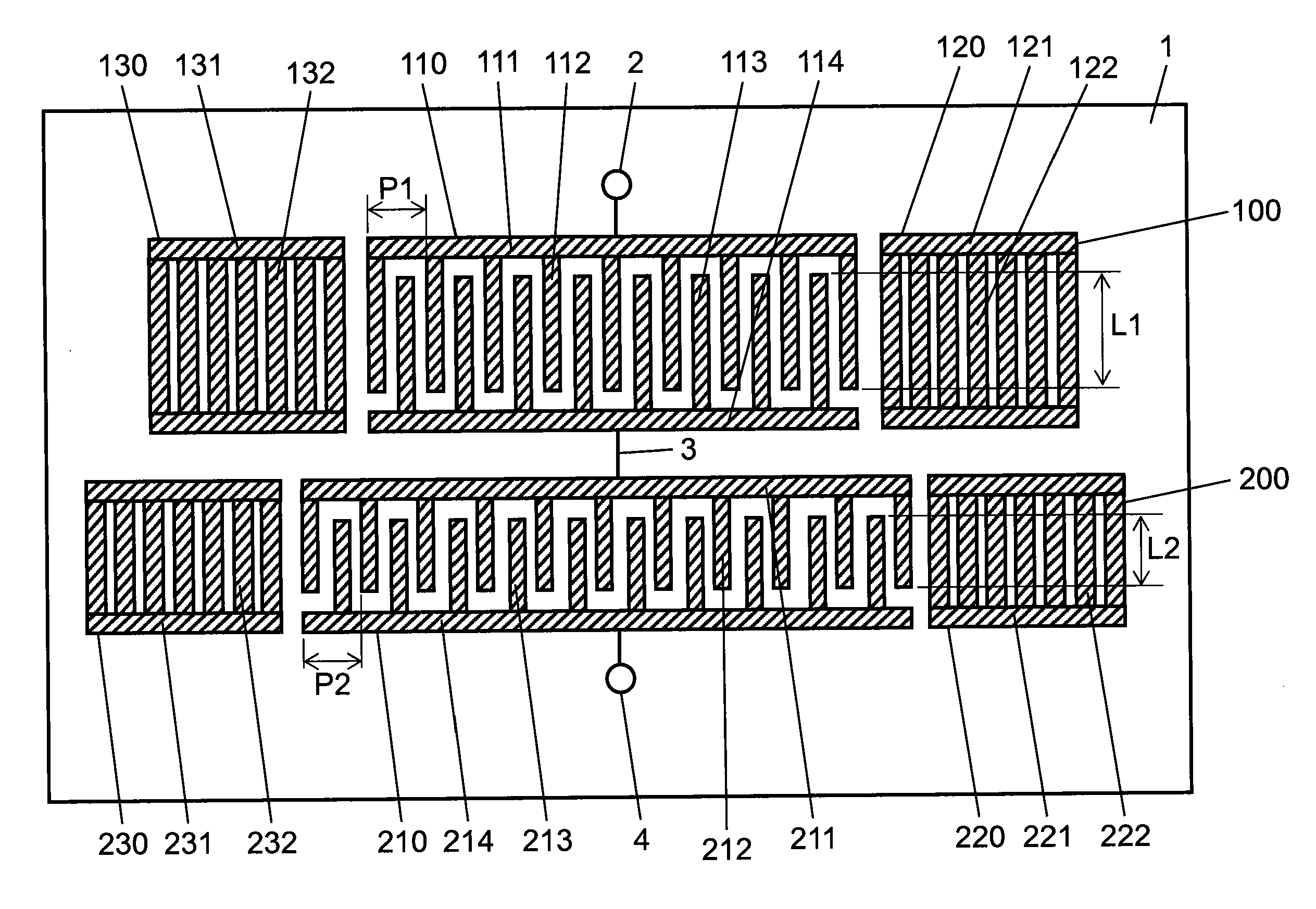
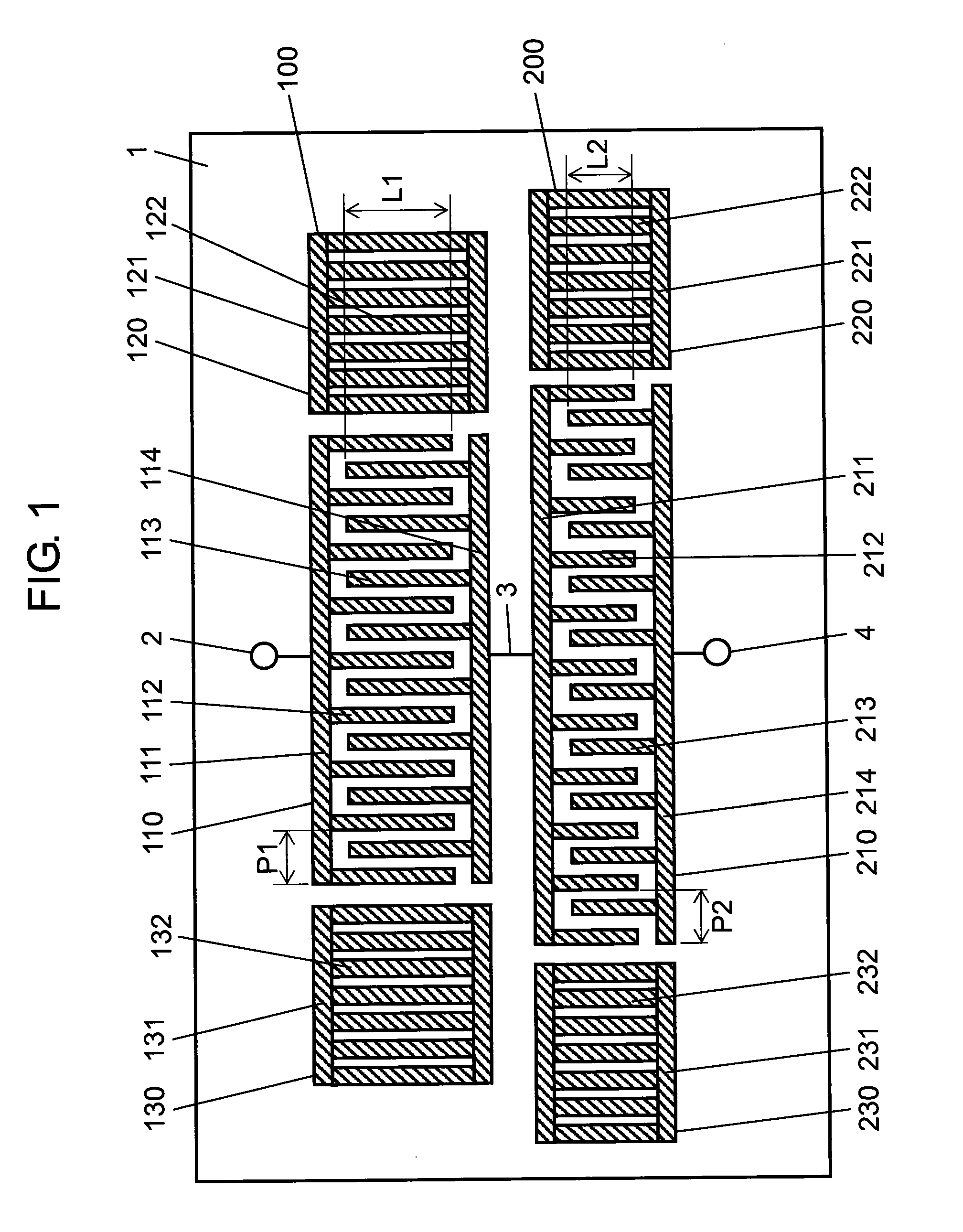
[0043]FIG. 1 is a top view showing an acoustic wave resonance device in accordance with a first exemplary embodiment of the present invention. As shown in FIG. 1, the acoustic wave resonance device of this exemplary embodiment includes piezoelectric substrate 1 made of lithium niobate, and first acoustic wave resonator 100 and second acoustic wave resonator 200 provided on an upper surface of piezoelectric substrate 1. First acoustic wave resonator 100 and second acoustic wave resonator 200 are cascade-connected.

[0044]First acoustic wave resonator 100 includes interdigital transducer electrode 110 and grating reflectors 120 and 130. Grating reflectors 120 and 130 are disposed such that they sandwich interdigital transducer electrode 110 therebetween on an acoustic wave propagation path.

[0045]Interdigital transducer electrode 110 includes bus bar 111 and a plurality of comb-shaped electrodes 112 that have the same length and are electrically connected to each other to bus bar 111. Co...

second exemplary embodiment

[0068]A second exemplary embodiment is different from the first exemplary embodiment in that interdigital transducer electrode 110 and interdigital transducer electrode 210 are connected in parallel.

[0069]FIG. 5 is a top view showing an acoustic wave resonance device in accordance with the second exemplary embodiment of the present invention. The acoustic wave resonance device shown in this exemplary embodiment includes piezoelectric substrate 1 made of lithium niobate, and first acoustic wave resonator 100 and second acoustic wave resonator 200 provided on an upper surface of piezoelectric substrate 1 as shown in FIG. 5. First acoustic wave resonator 100 and second acoustic wave resonator 200 are connected in parallel.

[0070]First acoustic wave resonator 100 includes interdigital transducer electrode 110 and grating reflectors 120 and 130. Grating reflectors 120 and 130 are disposed such that they sandwich interdigital transducer electrode 110 therebetween on an acoustic wave propag...

third exemplary embodiment

[0089]An acoustic wave filter in accordance with a third exemplary embodiment of the present invention is described with reference to drawings. In the third exemplary embodiment, a plurality of interdigital transducer electrodes is disposed between two grating reflectors.

[0090]FIG. 8 is a top view showing an acoustic wave filter in accordance with the third exemplary embodiment of the present invention. In FIG. 8, first acoustic wave resonator 300 includes interdigital transducer electrodes 311, 312, 313, 314, and 315 having an overlap width of L1 and grating reflectors 316 and 317 on the upper surface of a piezoelectric substrate. Interdigital transducer electrodes 311, 312, 313, 314, and 315 are disposed on the acoustic wave propagation path with an overlap width of L1 (overlap width L1 of comb-shaped electrodes of first acoustic wave resonator 300). The comb-shaped electrodes of interdigital transducer electrodes 311, 312, 313, 314, and 315 are disposed at pitches of P8, P9, P10,...


PUM


Abstract

An acoustic wave resonance device includes: piezoelectric substrate (1), first acoustic wave resonator (100) provided on an upper surface of piezoelectric substrate (1) and including first interdigital transducer electrode (110), and second acoustic wave resonator (200) provided on piezoelectric substrate (1) and including second interdigital transducer electrode (210). First acoustic wave resonator (100) and second acoustic wave resonator (200) are connected to each other. An overlap width of a plurality of first comb-shaped electrodes (112) forming first acoustic wave resonator (100) is larger than an overlap width of a plurality of second comb-shaped electrodes (212) forming second acoustic wave resonator (200). With such a configuration, frequencies in which a transverse mode spurious response is generated can be distributed and loss can be reduced.

Description

RELATED APPLICATIONS[0001]This application is a continuation-in-part of PCT / JP2008 / 003173 filed on Nov. 5, 2008 which claims priority under 35 U.S.C. §119 to Japanese Patent Application Nos. 2007-288351 filed on Nov. 6, 2007 and 2007-296523 filed Nov. 15, 2007. This application also claims priority to Japanese Patent Application No. 2009-096831 filed on Apr. 13, 2009. The entire contents of these applications are hereby incorporated by reference.BACKGROUND OF THE INVENTION[0002]1. Field of the Invention[0003]The present invention relates to an acoustic wave filter used in mobile communication equipment and the like.[0004]2. Description of the Related Art[0005]As a conventional acoustic wave filter, as shown in FIG. 19, for example, a configuration in which three acoustic wave resonators D, E, and F are connected in series has been known. With such a configuration, a voltage applied to each pair of comb-shaped electrode fingers is reduced and a mechanical stress intensively applied i...

Claims


Application Information

Patent Timeline
Patent Type & Authority Applications(United States)
IPC IPC(8): H01P5/12H03H9/17
CPCH03H9/0071H03H9/6496H03H9/6483H03H9/02944
Inventor GOTO, REIHAMAOKA, YOSUKENAKAMURA, HIROYUKITSURUNARI, TETSUYAFUJIWARA, JOJI
Owner SKYWORKS PANASONIC FILTER SOLUTIONS JAPAN
Why Eureka
Try Eureka