User interface device

a user interface and device technology, applied in the field of user interface devices, can solve the problems of difficult to accurately determine the actual shape of the hand, difficult to improve the accuracy of locating the fingertip position, and erroneous fingertip position, so as to improve the degree of approximation and determine the mounting direction comparatively easily

Inactive Publication Date: 2010-08-05
DENSO CORP
View PDF9 Cites 37 Cited by
  • Summary
  • Abstract
  • Description
  • Claims
  • Application Information

AI Technical Summary

Benefits of technology

[0012]It is an object of the present invention to provide a user interface device which can ignore things other than a hand correctly.
[0013]It is another object of the present invention to provide a user interface device which can provide sufficient accuracy for locating a fingertip position.
[0014]It is still another object of the present invention to provide a user interface device which can provide sufficient accuracy for locating a fingertip position by a simple algorithm.

Problems solved by technology

According to the method disclosed in the patent documents 2 or 3, there may be a problem to detect something other than a hand as a fingertip erroneously.
In the method disclosed in the patent document 4, since the imaging direction of a hand is not fixed, it is almost impossible to improve accuracy of locating a fingertip position.
In detail, it is difficult to correctly determine an actual shape of a hand based on a ratio of areas for each sub-rectangular areas and a color of a hand area.
Especially, it is difficult to correctly determine a fingertip area, because it is impossible to know a direction in which the fingertip area appears.
Therefore, an operator may feel a strong uncomfortable feeling.

Method used


Image

  • User interface device
  • User interface device
  • User interface device

Examples


first example

[0159]In a case that the pointer image data is initially described in a bit map data form, the input screen image frame data and the pointer image frame data can be compounded by using the alpha blending processing among corresponding pixels. As a result, it is possible to display the pointer image on the input screen image in an overlapping form in which the pointer image can be transparently seen.

second example

[0160]In a case that the pointer image data is described in a vector outline data form, it is possible to employ a method which comprises a step for generating an outline of a pointer image using the pointer image frame data, a step for generating a bit map data which is generated by rasterizing an inner area of the outline, and a step for performing the same alpha blending processing as described in the first example.

third example

[0161]It is possible to employ a method which comprises a step for drawing an outline on an input screen image frame using the vector outline data which forms the pointer image data, a step for extracting pixels on the input screen image corresponding to the inside of the outline, and a step for shifting values of the extracted pixels uniformly.

[0162]In the first through third examples, the pointer image may be displayed in a form in which the outline is emphasized. For example, a pixel which form the outline of the pointer image data may be displayed in an emphasized manner by increasing a blend ratio of the pointer image data. In addition, it is also possible to make the pointer image data into the image data of only the outline described by the bit map data form or the vector outline data form, and to display only the outline in an overlapping manner.

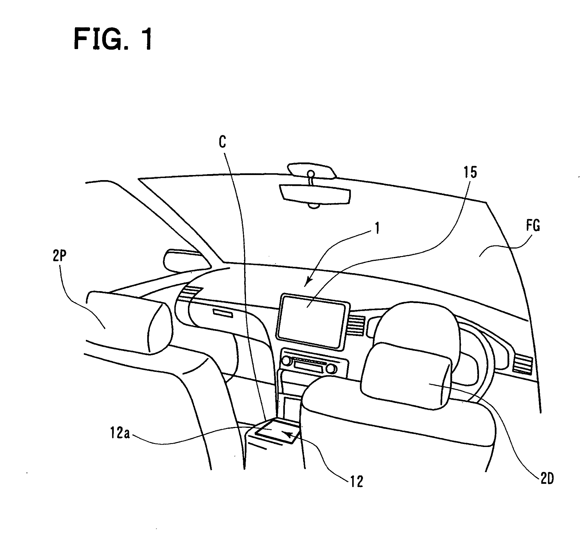
[0163]As shown in FIG. 1, the screen of the monitor 15 is disposed away from a direction for looking a finger on the touch panel 12...


PUM


Abstract

A user interface device detects a fingertip placed on an imaging range. The imaging range is located or arranged so that a user inserts and place a hand along a predetermined direction. A device detects a tip area corresponding to the fingertip from the imaging range. The device determines whether the detected tip area is a finger or not. The determination can be performed by evaluating a size of the tip area, for example, whether the width is in an appropriate range or not. If the tip area is verified as a finger, a position of the fingertip is calculated. According to the device, it is possible to determine whether it is a finger or not by using a relatively simple algorithm. As a result, it is possible to eliminate objects other than finger and to provide sufficient accuracy for detecting the fingertip.

Description

CROSS REFERENCE TO RELATED APPLICATION[0001]This application is based on Japanese Patent Application No. 2009-20636 filed on Jan. 30, 2009, the contents of which are incorporated herein by reference in its entirety.FIELD OF THE INVENTION[0002]The present invention relates to a user interface device.BACKGROUND OF THE INVENTION[0003]Conventionally, a user interface device for a vehicle mounted device, such as a car navigation system, is proposed. In such a proposed device, a hand of an operator is taken as an image by a camera, then, the device extracts a finger image from the image data, and displays the extracted finger image area on an input display screen of GUI, Graphical User Interface system, for the vehicle mounted device. For example, the extracted finger image area is displayed on a screen of the car navigation system. For example, the following patent document 1 discloses a device which uses a camera attached on a ceiling of the vehicle. In this device, the camera takes an ...

Claims


Application Information

Patent Timeline
Patent Type & Authority Applications(United States)
IPC IPC(8): G06F3/042G06F3/033G06F3/0354G06F3/038G06F3/041
CPCG06F3/042G06F2203/04808G06F3/04883G06F3/0425
Inventor KAWASHIMA, TAKESHINAGATA, TAKASHI
Owner DENSO CORP
Why Eureka
Try Eureka