Object motion capturing system and method

a technology of motion capture and object, applied in the field of object motion capture system and method, can solve the problems of incomplete or at least unreliable corresponding motion capture, inability to track, and inability to solve the problem altogether, so as to achieve accurate and reliable measurement of motion characteristics

Inactive Publication Date: 2010-08-05
KONINKLIJKE PHILIPS ELECTRONICS NV
View PDF7 Cites 86 Cited by
  • Summary
  • Abstract
  • Description
  • Claims
  • Application Information

AI Technical Summary

Benefits of technology

[0008]It is desirable to provide a motion capture system and method which can accurately and reliably measure motion characteristics, like position, orientation, velocity, acceleration over time, also when the object moves out of the line-of-sight of a camera.

Problems solved by technology

In the above-mentioned first type of system using one or more optical markers to capture motion of an object a problem arises when an optical marker moves out of the field of view of a camera intended to register the movement of the optical marker, or still is in the field of view of the camera but hidden (out of line-of-sight) behind another optical marker, a part of the object, or another object.
In such situations, the camera is unable to track the optical marker, and the corresponding motion capture becomes incomplete or at least unreliable.
A possible solution to this problem is the use of multiple cameras, however, this will not solve the problem altogether, is very expensive, and adds to the complexity of the motion capture system.
In the above-mentioned second type of system using motion sensors to capture motion of an object a problem arises when a motion sensor position cannot be determined accurately by lack of reference or calibration positions over an extended period of time.
Even if an initial position of a motion sensor is calibrated, during movement of the motion sensor in time the position and orientation will very soon have such large errors that the motion sensor motion data become unreliable.

Method used


Image

  • Object motion capturing system and method
  • Object motion capturing system and method

Examples


Embodiment Construction

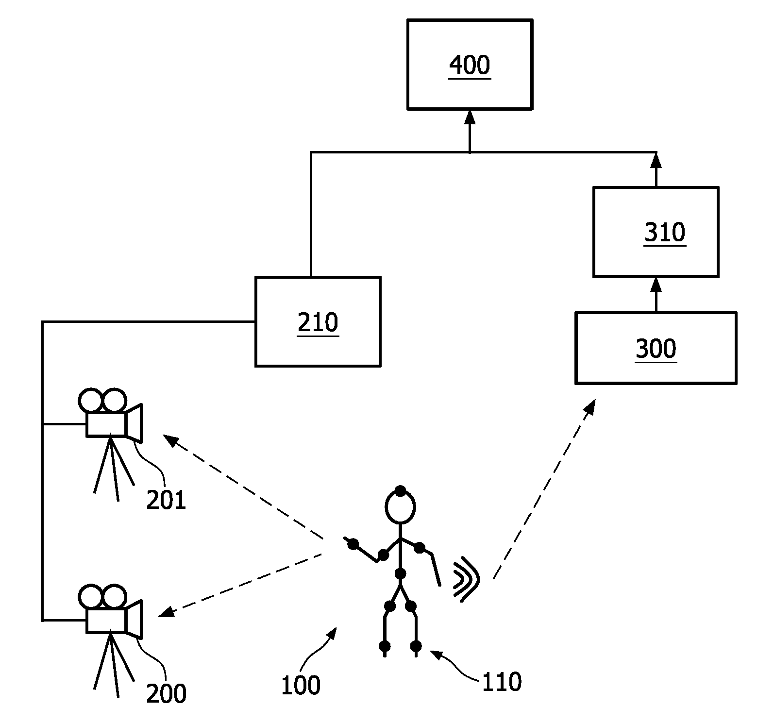
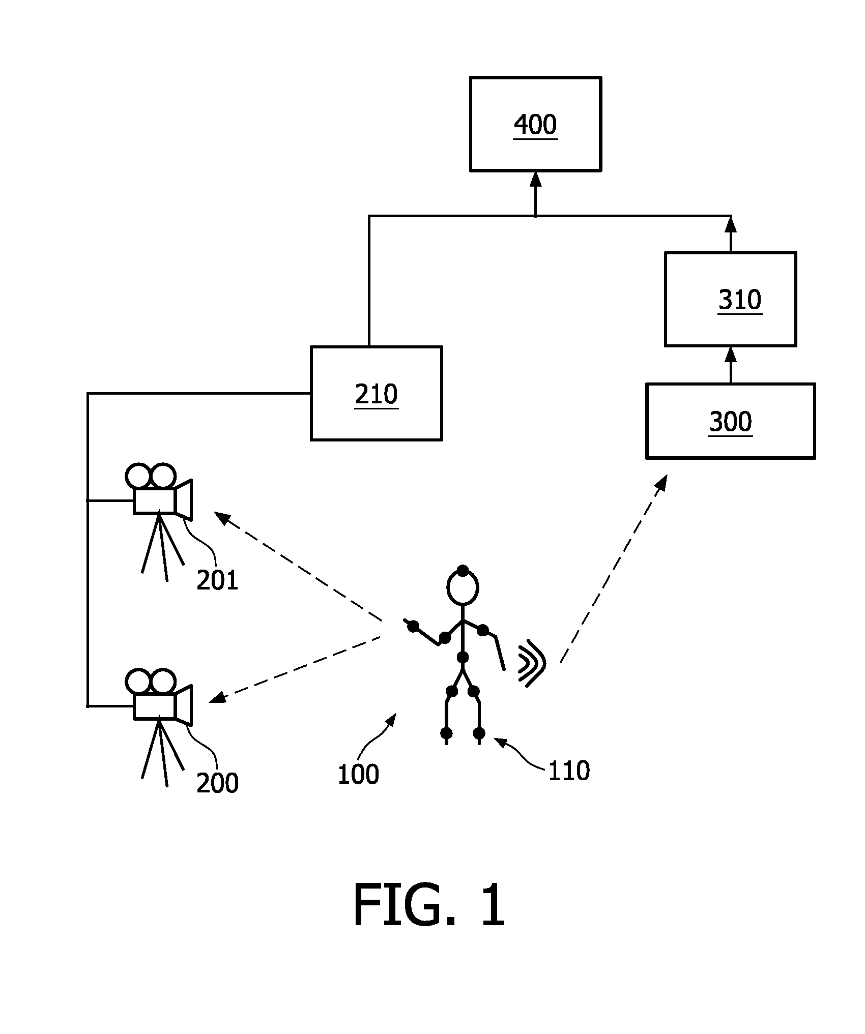
[0014]FIG. 1 shows a diagram indicating components of a system of capturing motion of an object 100. In the example of FIG. 1, the object 100 is to represent a person. However, the object 100 may also be an animal, a plant, or a device. The object may be moving as a whole, such as performing a translational and / or rotational movement, and / or the object may have different parts moving relative to each other. The following description will focus on a person moving, but it will be clear that the system described is not limited to capturing motion of a person.

[0015]The object 100 as shown in FIG. 1 has different parts movable relative to each other, such as a head, a body, arms and legs. As schematically indicated, by way of example the head and the body of the object 100 are each provided with one tracking device 110, whereas each arm and each leg are provided with two tracking devices 110.

[0016]The tracking device 110 comprises a motion sensor. The motion sensor may comprise at least ...


PUM


Abstract

In a system and method of capturing movement of an object, a tracking device is used having an optical marker and a motion sensor providing motion data representative of the position and orientation of the tracking device. The tracking device is connected to the object, and motion of the optical marker is registered by a camera to thereby provide video data representative of the position of the tracking device. The motion data and the video data are processed in combination to determine the position and orientation of the tracking device in space over time.

Description

FIELD OF THE INVENTION[0001]The present invention relates to a system and method of capturing motion of an object.BACKGROUND OF THE INVENTION[0002]In many fields, such as the field of sports, the field of healthcare, the field of movies and animation, and the field of rehabilitation, capturing a motion of a moving object plays a vital role. Once the motion has been captured, different motion characteristics can be determined, such as position in time, velocity, acceleration, distance, time of flight, spin rate and so on. The object may be a person, an animal, a plant or any non-living device. The motion may be a motion of the object as a whole, or a motion of a part of the object, or a combination of such motions, where different parts of the object may perform different motions at the same time.[0003]Considerable technical developments have been made to capture motion in relation to sports, e.g. the motion of sportsmen and sportswomen (like athletes), the motion of sports or game o...

Claims


Application Information

Patent Timeline
Patent Type & Authority Applications(United States)
IPC IPC(8): H04N7/18
CPCA61B5/1127A61B2562/0219A63B24/0006A63B2220/803G06T2207/30196G06F3/011G06T7/2033G06T2207/10016A63B2220/806G06T7/246
Inventor PASVEER, WILLEM FRANKEVAN ACHT, VICTOR MARTINUS GERARDUS
Owner KONINKLIJKE PHILIPS ELECTRONICS NV
Why Eureka
Try Eureka