Eureka AIR delivers breakthrough ideas for toughest innovation challenges, trusted by R&D personnel around the world.

Mobile radio terminal and radio communication method

a mobile radio terminal and radio communication technology, applied in the field of mobile radio terminals, can solve the problems of not supporting 1tt under the current 3gpp standards, affecting the efficiency of radio communication, and taking a long time to establish a communication link, etc., and achieve the effect of efficient in a short tim

Inactive Publication Date: 2010-08-05
FUJITSU TOSHIBA MOBILE COMM LTD
View PDF41 Cites 47 Cited by
  • Summary
  • Abstract
  • Description
  • Claims
  • Application Information

AI Technical Summary

Benefits of technology

[0012]The present invention has been accomplished to solve the above-described problems. The object of the present invention is to provide a mobile radio terminal and radio communication method, capable of transiting to a communication system in a CDMA mode, efficiently in a short time, under an instruction from a communication system in an LTE mode.
[0019]The present invention can therefore provide a mobile radio terminal and radio communication method, capable of transiting to a communication system in the CDMA mode, efficiently in a short time, under an instruction from a communication system in the LTE mode.

Problems solved by technology

For this reason, the mobile station needs to perform a process of capturing the system from the first step, over the 1×TT network, and it takes much time to establish a communication link and much delay time occurs before the communication starts.
In this process, however, the 1×TT is not supported under the current 3GPP standards.
The conventional mobile radio terminal corresponding to a plurality of communication system has a problem that it takes much time to transit to the CDMA communication system under instructions from the LTE communication system.

Method used


Image

  • Mobile radio terminal and radio communication method
  • Mobile radio terminal and radio communication method
  • Mobile radio terminal and radio communication method

Examples


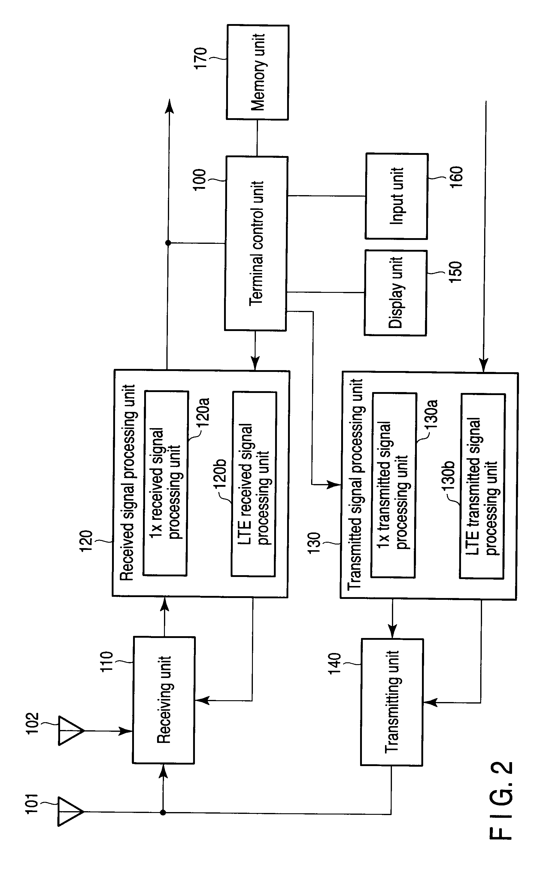
Embodiment Construction

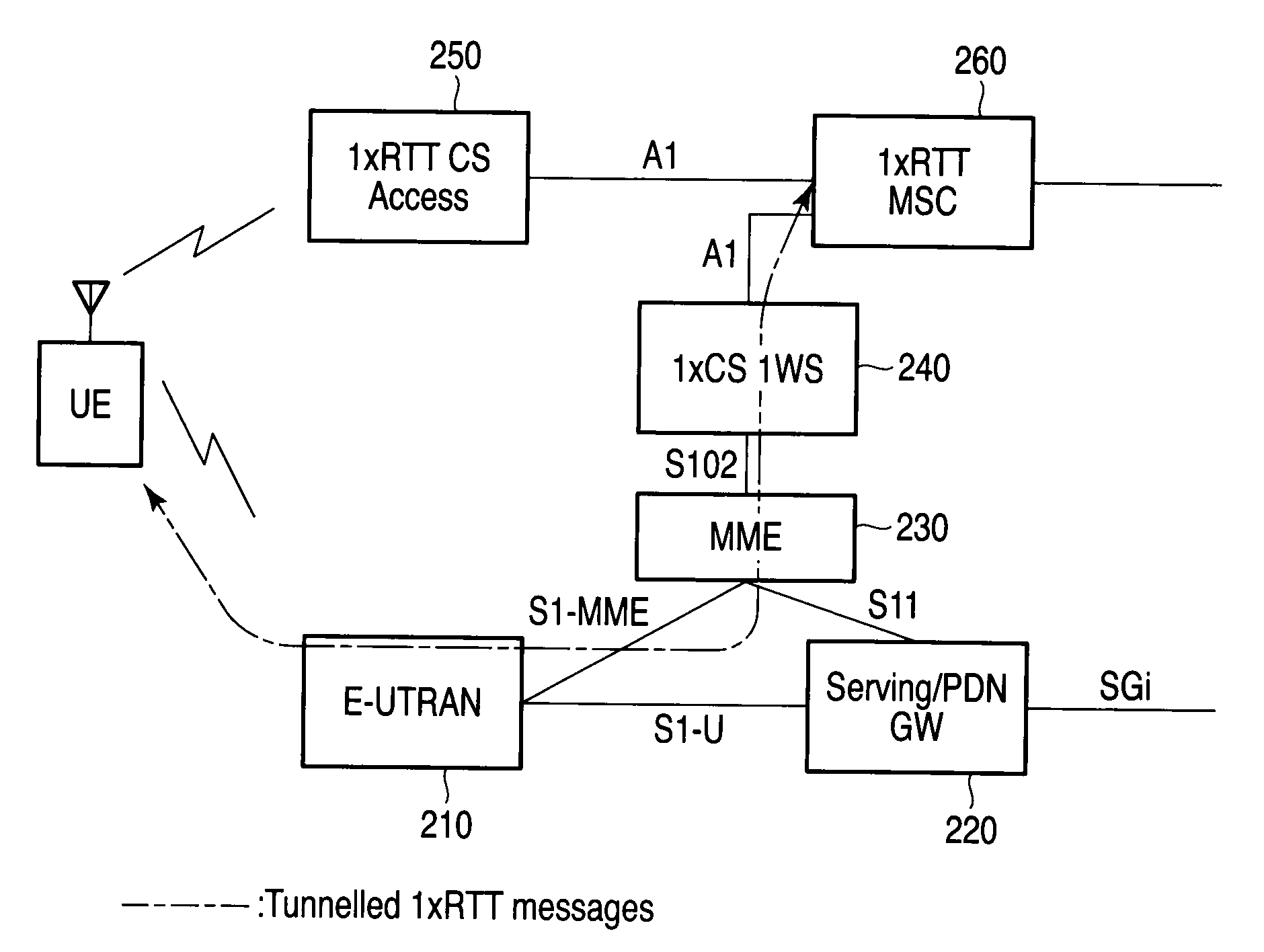
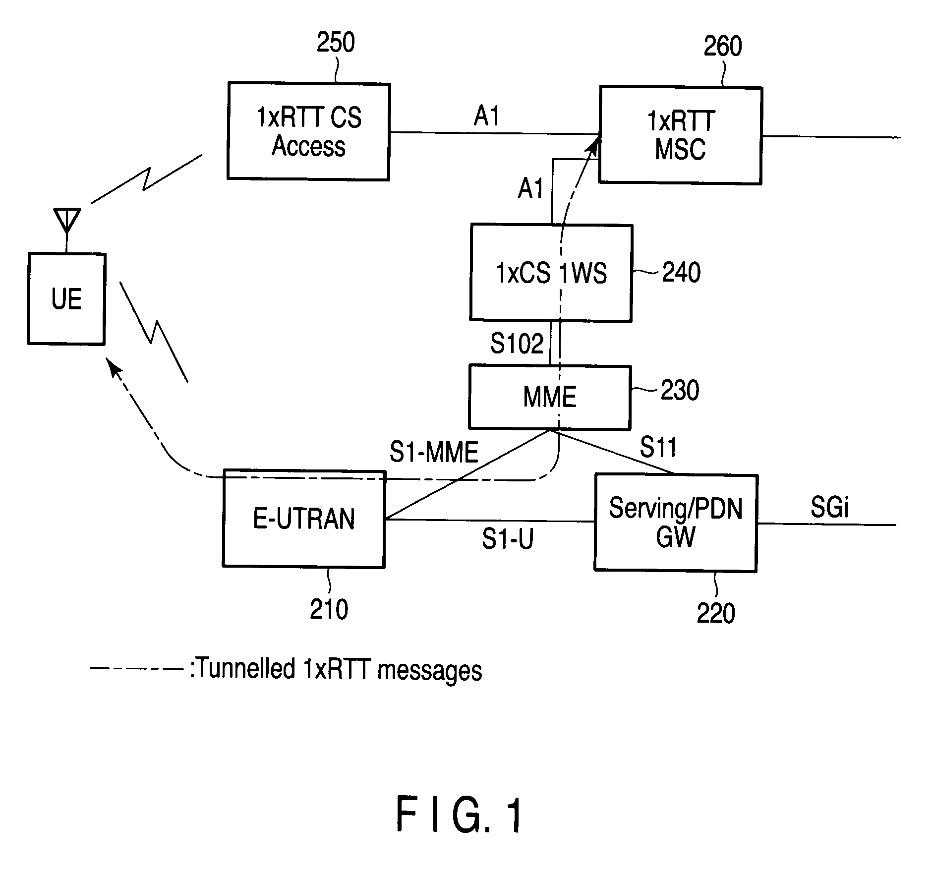
[0032]Embodiments of the present invention are explained below with reference to the accompanying drawings.

[0033]The embodiments relate to mobile radio terminal UE, i.e. a mobile station. The mobile radio terminal UE is capable of performing communications in two or more different radio connection modes.

[0034]In the following descriptions, for example, the mobile radio terminal UE corresponds to two radio connection modes, CDMA2000 1× mode (hereinafter called 1× mode) and LTE (Long Term Evolution) mode.

[0035]The 1× mode is capable of offering speech communication service and low-speed packet communication service at 100 kbps or lower. On the other hand, the LTE mode offers high-speed packet service at approximately 2 Mbps to 20 Mbps by packet switching connection and is also capable of offering the speech communication service by VoIP (Voice over Internet Packet).

[0036]In each of the modes, mutually different available frequencies are determined which are defined in the following ma...


PUM


Abstract

A mobile radio terminal UE performs starting PNG, detecting a best cell, and starting generation of Long Code and receives various types of messages from a 1×RTT CS Access on the basis of System Information supplied from an E-UTRAN.

Description

CROSS-REFERENCE TO RELATED APPLICATIONS[0001]This application is based upon and claims the benefit of priority from prior Japanese Patent Application No. 2009-020695, filed Jan. 30, 2009, the entire contents of which are incorporated herein by reference.BACKGROUND OF THE INVENTION[0002]1. Field of the Invention[0003]The present invention relates to a mobile radio terminal used for, for example, a moving body.[0004]2. Description of the Related Art[0005]In radio communication systems of, for example, a mobile telephone system and a wireless LAN, OFDMA (Orthogonal Frequency Multiple Access) and CDMA (Code Division Multiple Access) are employed as communication schemes. OFDM (Orthogonal Frequency Division Multiplexing) is proof against interference or disturbance and is therefore noticed.[0006]In 3GPP LTE (Long Term Evolution) employing the OFDM (see, for example, Erik Dahlman “Academic Press”, 2007, pp. 277-369, 3GPP TS23.401, 3GPP TS23.402, 3GPP TS36.300), entire data over a network ...

Claims


Application Information

Patent Timeline
Patent Type & Authority Applications(United States)
IPC IPC(8): H04W4/00H04B7/216H04J13/00H04W36/14H04W48/18H04W68/12
CPCH04W88/06H04W36/0022H04W36/00224
Inventor IIMORI, EIJI
Owner FUJITSU TOSHIBA MOBILE COMM LTD
Why Eureka
Eureka Blog
Learn More