
Fastening structure

Active Publication Date: 2010-08-05
TOYOTA JIDOSHA KK
View PDF12 Cites 15 Cited by
  • Summary
  • Abstract
  • Description
  • Claims
  • Application Information

AI Technical Summary

Benefits of technology

[0041]According to the present invention, a fastening structure can be provided that allow the bolt to be removed with a certainty while being difficult and time consuming to remove it in a narrow working space, and provide both the anti-theft function to prevent the attaching and attached objects fastened from being stolen and the ease of maintenance thereof.

Problems solved by technology

This results in the fact that the vehicle cannot be moved, thereby preventing the vehicle from being stolen.
However, in the case that the SBW motor, i.e., an actuator externally mounted on the case of the power transmission apparatus equipped with the parking lock mechanism is removed from the case, there is a possibility that the vehicle is stolen since the vehicle can be moved if the lock pawl of a swingable type to be brought out of engagement from the rotating member by tampering the parking lock mechanism.

Method used


Image

  • Fastening structure
  • Fastening structure
  • Fastening structure

Examples


first embodiment

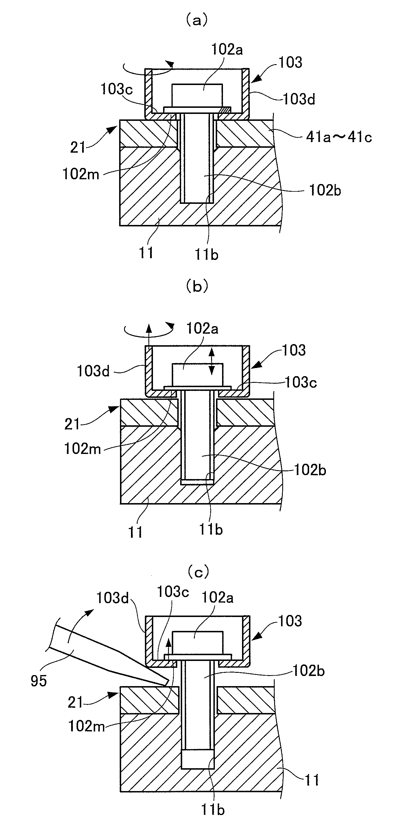
[0104]FIGS. 1 to 8 show a fastening structure according to a first embodiment of the present invention. The construction thereof will firstly be explained hereinafter.

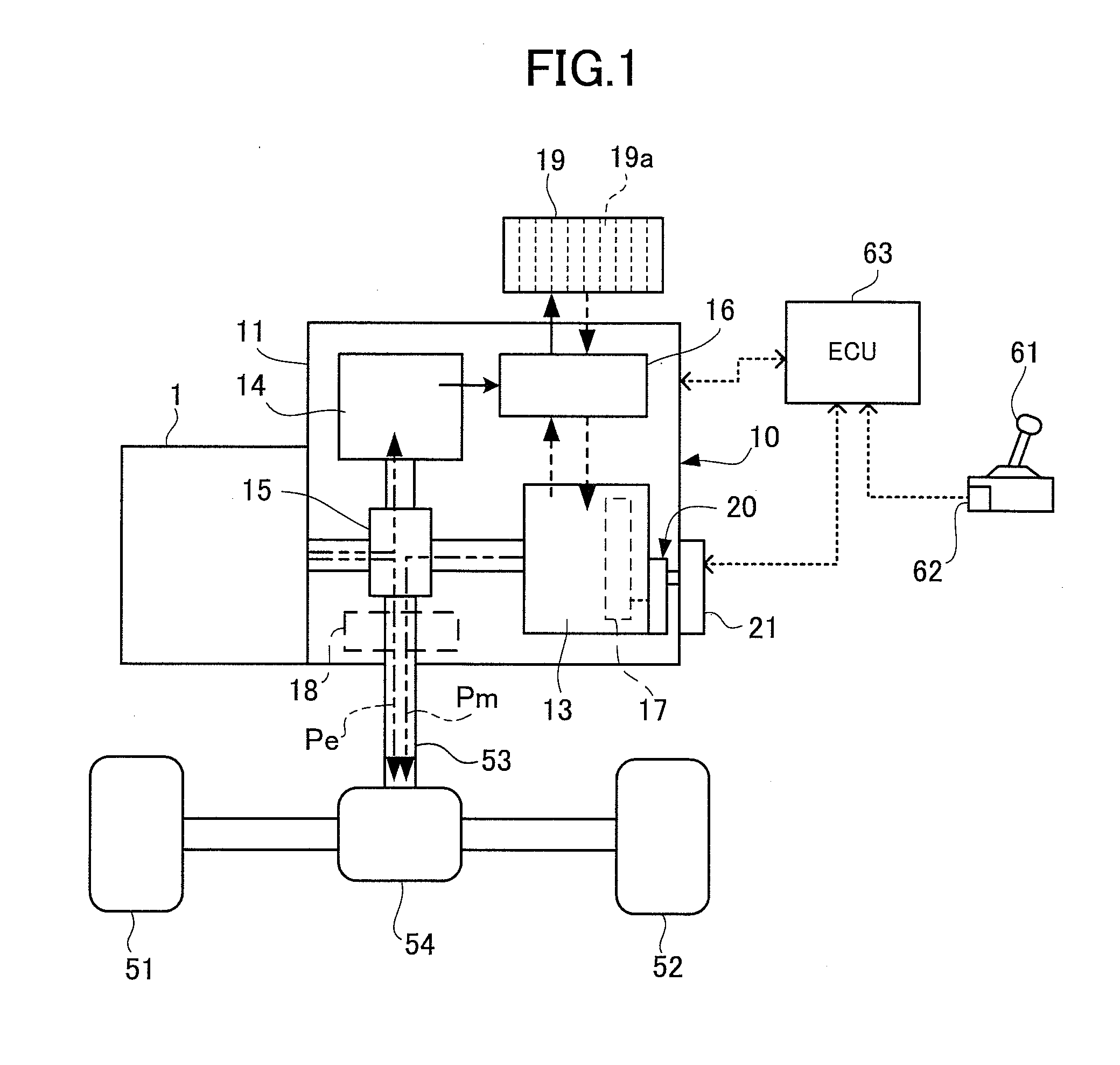
[0105]In FIG. 1, a power transmission apparatus 10 constituting an attached member is a hybrid transmission having a transmission case 11 constituting a case and connected to an engine 1 constituting a prime mover of an automotive vehicle. In the transmission case 11 is accommodated an electric motor 13 of an AC synchronous type, a generator 14, a power splitting mechanism 15, and an inverter 16.

[0106]The electric motor 13 is constituted by a generator-motor which can be driven by a battery pack 19 mounted on the vehicle and can charge the battery pack 19 when regeneration brake is operated. The generator 14 is adapted to generate power when driven by the engine 1, while the power thus generated is stored in the battery pack 19.

[0107]The battery pack 19 is for example constituted by a plurality of battery modules 19a c...

second embodiment

[0188]FIGS. 13 to 15 show a fastening structure according to a second embodiment of the present invention. The construction of the power transmission apparatus will be explained with reference to the drawings the same as those of the first embodiment.

[0189]The fastening device 131 is shown in FIG. 13 to comprise a bolt 132 having a head portion 132a and a threaded portion 132b integrally formed with the head portion 132a, a bottomed tubular bolt cover 133 having an opening end 133a, and a cap member 134 for closing the opening end 133a of the bolt cover 133. FIG. 13(a) shows a cross-sectional view of the fastening device 131 with the cap member 134 not being attached to the bolt cover 133, and FIG. 13(b) shows a cross-sectional view of the fastening device 131 with the cap member 134 being attached to the bolt cover 133.

[0190]The head portion 132a of the bolt 132 has a fitting groove formed in a polygonal shape (female head) to be fitted with a wrench such as a hexagonal wrench so t...

third embodiment

[0224]FIGS. 16 and 17 show a fastening structure according to a third embodiment of the present invention. The explanation of the third embodiment will be omitted with the elements and parts same as those of the second embodiment bearing the same reference numerals as those of the second embodiment. The construction of the power transmission apparatus will be explained with reference to the drawings the same as those of the first embodiment.

[0225]The fastening device 141 is shown in FIG. 16 to comprise a bolt 142 having a head portion 142a and a threaded portion 142b integrally formed with the head portion 142a, the bottomed tubular bolt cover 133 having the opening end 133a, and the cap member 134 for closing the opening end 133a of the bolt cover 133.

[0226]The head portion 142a of the bolt 142 has a fitting groove formed in a polygonal shape (female head) to be fitted with a wrench such as a hexagonal wrench so that the head portion 142a of the bolt 142 is rotated in clamping-down...


PUM


Abstract

An anti-theft fastening device for fastening an SBW motor externally mounted to a transmission case includes a bolt having a head portion and a threaded portion integrally formed with the head portion, a bottomed tubular bolt cover having an opening end, and a cap member closing the opening end of the bolt cover. The bolt cover has a through bore to have the threaded portion of the bolt pass through, a bottom portion abutting a bottom surface of the head portion of the bolt, and a grip portion projecting from an outer circumference of the bottom portion and surrounding a periphery of the head portion of the bolt. When the threaded portion of the bolt is screwed into a threaded groove of the transmission case, the bottom portion of the bolt cover is interposed between the bottom surface of the head portion and each fastening portion of a bracket portion.

Description

[0001]This application is a Continuation of International Application No. PCT / JP2008 / 002870 filed Oct. 10, 2008, claiming priority based on Japanese Patent Application No. 2007-266937 filed Oct. 12, 2007 and Japanese Patent Application No. 2008-108103 filed Apr. 17, 2008, the contents of all of which are incorporated herein by reference in their entirety.BACKGROUND[0002]1. Field of Invention[0003]The present invention relates to a fastening structure and, in particular, to a fastening structure for the purpose of fastening an attaching member to an attached member with a fastening device used for this purpose.[0004]2. Background Art[0005]The fastening device of this kind such as for example a bolt and the like has so far been known to be used for fastening the attaching member to the attached member. The fastening device is generally designed to be firmly coupled with the attaching and attached members and by no means intended to be removed from the attaching and attached members to...

Claims


Application Information

Patent Timeline
IPC IPC(8): F16B37/14
CPCF16B23/0053F16B23/0076F16B35/06F16H2061/326F16B41/005F16H61/32F16H63/3466F16B37/14F16B41/002
Inventor MIYAGAWA, TAKESHINOMASA, HITOSHI
Owner TOYOTA JIDOSHA KK
Features
  • Generate Ideas
  • Intellectual Property
  • Life Sciences
  • Materials
  • Tech Scout
  • Unparalleled Data Quality
  • Higher Quality Content
  • 60% Fewer Hallucinations
Learn More