
Integrated voltage and var optimization process for a distribution system

a technology of integrated voltage and var, applied in the direction of process and machine control, automatic control of ignition, instruments, etc., can solve the problems of energy loss, voltage regulation affecting the effective loading of feeders, loss of current, etc., and achieve the effect of small, simplified academic models

Active Publication Date: 2010-08-05
HITACHI ENERGY SWITZERLAND AG
View PDF7 Cites 52 Cited by
  • Summary
  • Abstract
  • Description
  • Claims
  • Application Information

AI Technical Summary

Benefits of technology

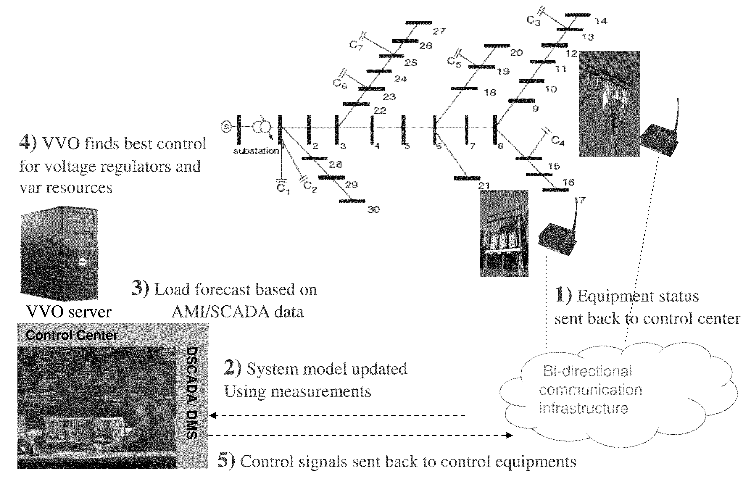
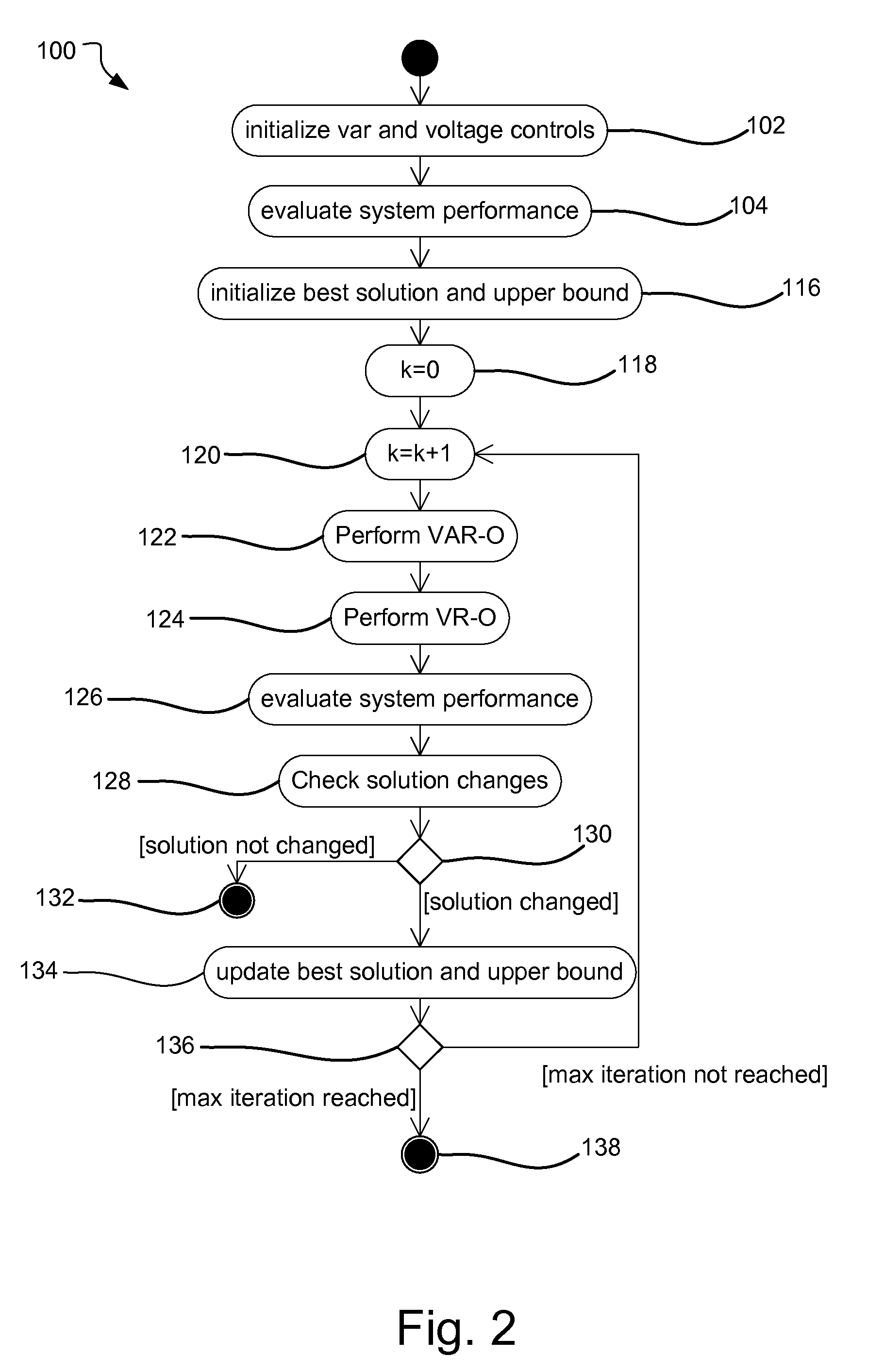
The present invention provides a method for determining the optimal settings for voltage regulating transformers and capacitor bank switches in a distribution network. The method involves receiving a network model and determining state and control variables. An objective function is used to calculate the overall objective value of the network under initial control variables. A var optimization calculation is performed to output an optimized set of control settings. A voltage optimization calculation is performed to output an optimal set of control settings. The system performance is evaluated using the optimal set of control settings. The process is repeated until the control values do not change or the objective function value does not change. The control values are then output to a distribution control system. The technical effect of this invention is to improve the efficiency and performance of distribution networks by optimizing the settings of voltage regulating transformers and capacitor bank switches.

Problems solved by technology

In electricity distribution systems, loss occurs when current flows through the conductors in the system.
Voltage regulation affects the effective loading of feeders, as well as the energy losses.
Most solution approaches proposed to date are applicable to small, very simplified academic models, and are not suitable for large scale, meshed, multi-source, multi-phase unbalanced distribution systems.
The limitations in the methods are due to (1) the model being too simplified (i.e. radial, balanced network, balanced load, single source) to represent a real system, (2) the computation efficiency being so low that the solution can not be scaled for either online or offline applications for large system, or (3) the optimization power is very limited.

Method used


Image

  • Integrated voltage and var optimization process for a distribution system
  • Integrated voltage and var optimization process for a distribution system
  • Integrated voltage and var optimization process for a distribution system

Examples


Embodiment Construction

[0018]The present invention relates to an integrated voltage and var optimization (IVVO) process. The purpose of IVVO is to find the optimal integer solution for the controllable taps of the voltage regulating transformers and the switchable capacitor / reactor banks to minimize the energy loss or the total demand on a distribution circuit.

[0019]In the description of the solution process, reference will be made to two categories of variables: the state variables and the control variables. The state variables are the phase specific voltages at every node of the system in either polar or rectangular coordinates. The state variable vector is designated by x. A node is a physical or conceptual connection point between different network elements, such as, for example, the connection point between a transformer and a section of overhead line or underground cable, or a point on a section of over-head line where a distribution service transformer is connected. Several phase specific voltage v...


PUM


Abstract

The method determines the optimal settings for the controllable taps ut of voltage regulating transformers and the capacitor bank switches uc in a distribution network. Var optimization is calculated with the controllable tap settings ut fixed at an initial value, or the best value found so far, to output an optimized set of control settings uc. Voltage optimization is calculated with the control settings uc fixed at the best solution found so far, to output an optimal set of control settings ut. Using an objective function, system performance is evaluated using the optimal set of control settings ut and uc and repeating the steps until either the control values ut and uc do not change from one iteration to the next, the objective function value does not change or if the new objective function value is greater than the last. The control values ut and uc are then output to a distribution control system.

Description

[0001]This application claims priority to provisional application no. 61 / 150185 filed on Feb. 5, 2009 the contents of which are incorporated in their entirety.BACKGROUND[0002]In electricity distribution systems, loss occurs when current flows through the conductors in the system. The energy loss through a conductor can be calculated according to I2R, where I is the current through a conductor whose resistance is R. The net demand and current flows on a distribution circuit depend on the loading and the voltage profile on the feeders. Net demand is the net energy delivered from the substations into the distribution circuits and is the summation of the total energy loss on all the conductors in the circuits and the total energy delivered at all load connection points. Reactive compensation can reduce unnecessary current flows attributable to reactive power flows and in turn reduce losses. Voltage regulation affects the effective loading of feeders, as well as the energy losses.[0003]V...

Claims


Application Information

Patent Timeline
Patent Type & Authority Applications(United States)
IPC IPC(8): G06F1/26G06F17/11
CPCH02J3/1828Y02E40/30H02J3/1878
Inventor FENG, XIAOMING
Owner HITACHI ENERGY SWITZERLAND AG
Learn More