Wireless particle collection system

a particle collection and wireless technology, applied in the direction of metal sawing accessories, separation processes, manufacturing tools, etc., can solve the problems of adverse noise, premature failure, and often tedious operation for users

Inactive Publication Date: 2010-08-12
CHANG TYPE INDAL
View PDF6 Cites 104 Cited by
  • Summary
  • Abstract
  • Description
  • Claims
  • Application Information

AI Technical Summary

Problems solved by technology

This operation was often tedious for the user since there was always a manual activation/deactivation involved with a distant dust collector.
Alternately, the tool user may leave the dust extraction unit on continuousl...

Method used


Image

  • Wireless particle collection system
  • Wireless particle collection system
  • Wireless particle collection system

Examples


Embodiment Construction

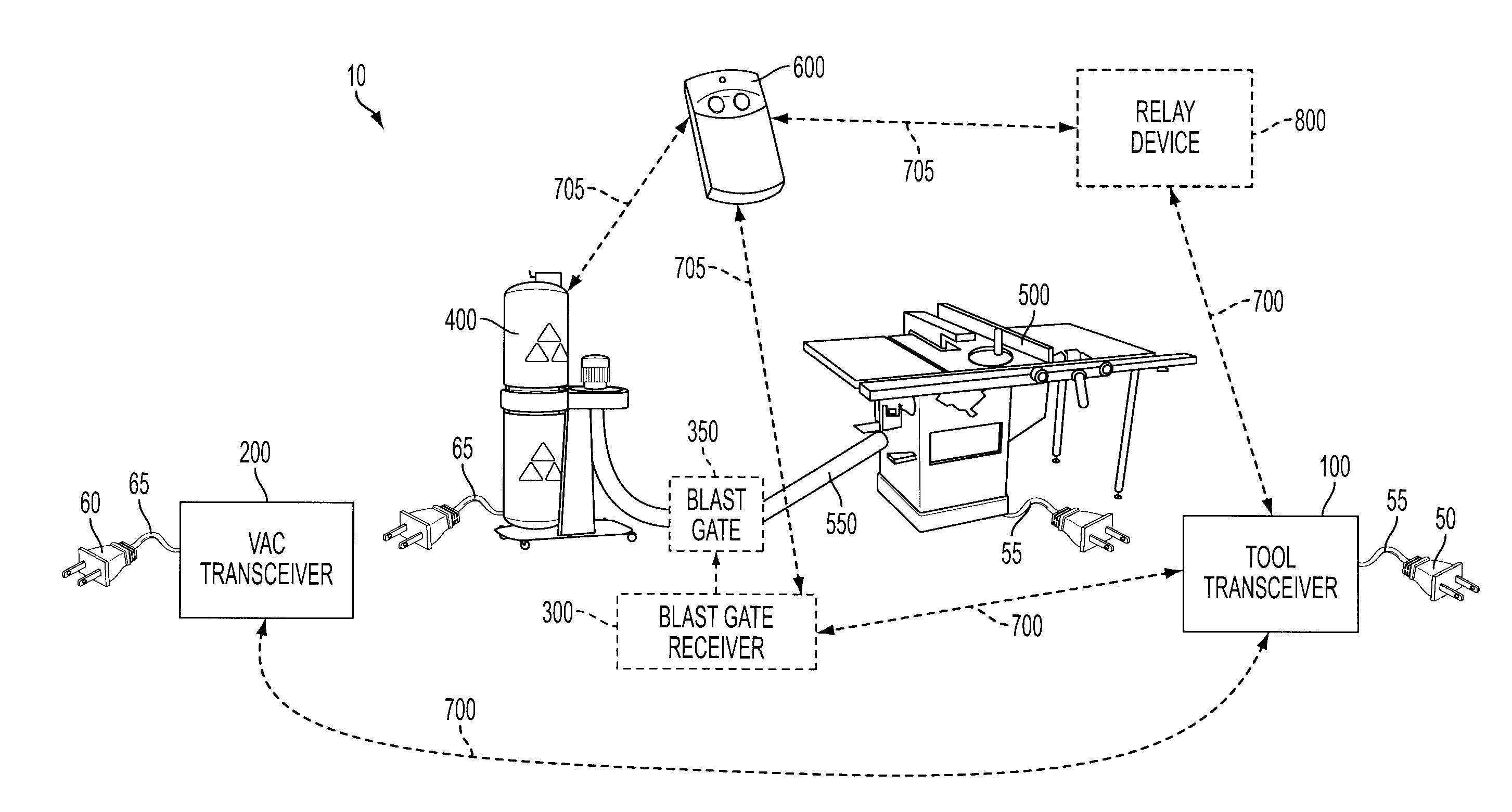
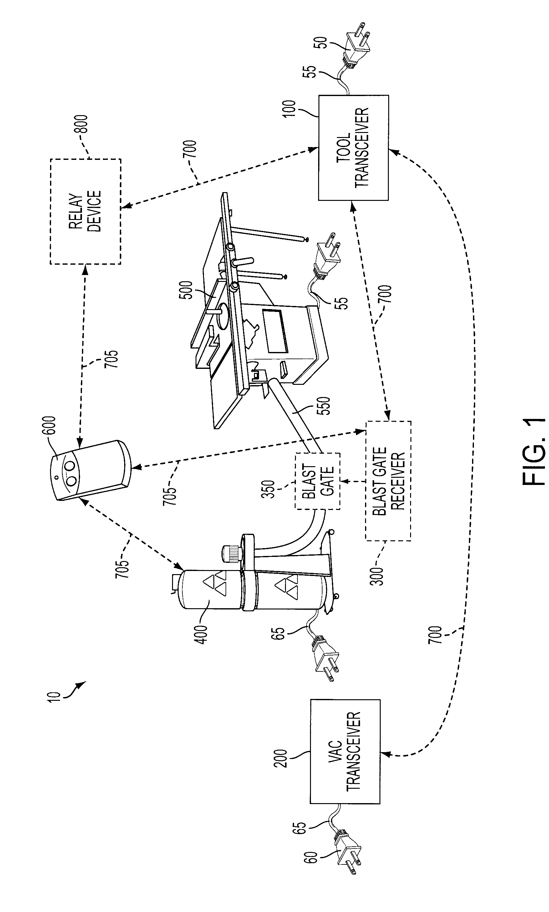
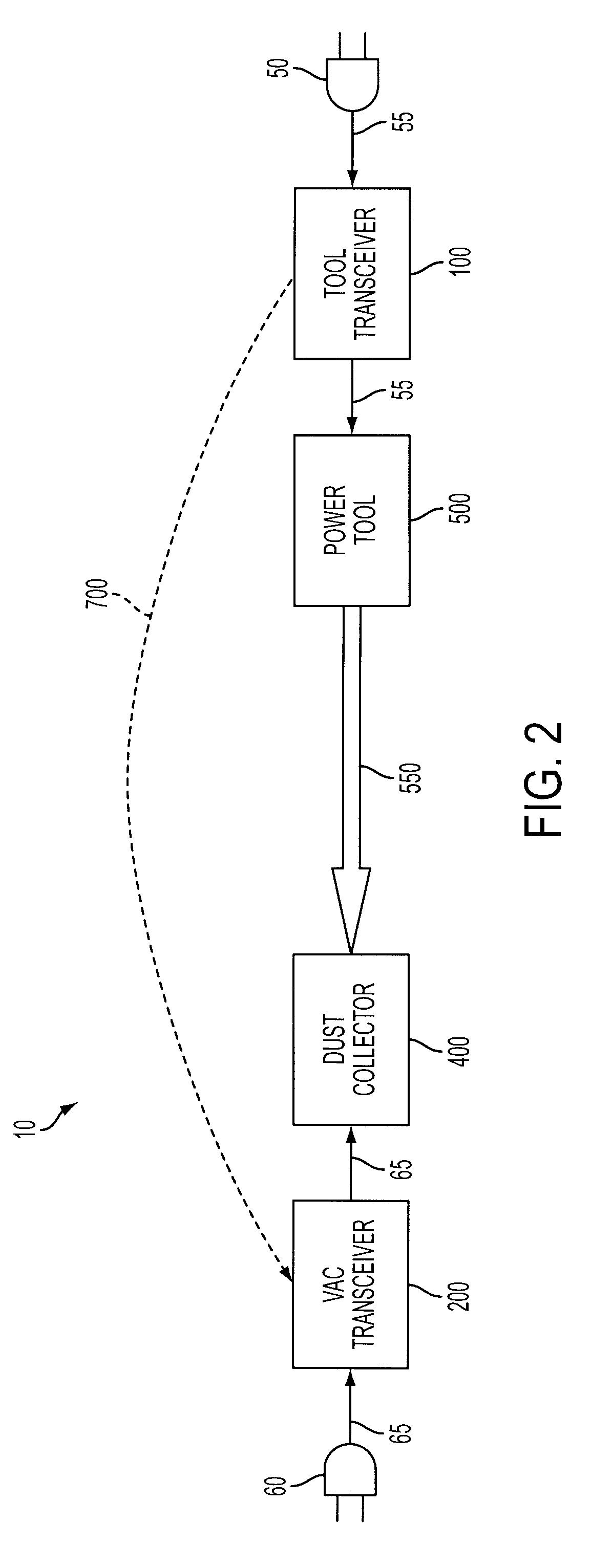
[0023]The example wireless particle collection system described in more detail hereafter senses power tool operation and remotely activates and / or deactivates a dust collector at optimum times. Activation of the dust collector may alternatively be accomplished manually via a key fob that is independent of tool operation.

[0024]The example system can be understood as a network of wireless, independent devices that can communicate with other devices in the network. The devices include a plurality of transceivers, with a given transceiver acting as a primary transmitter and other transceivers acting as receivers (“listening devices”). The primary transmitter, upon a tool activation event, broadcasts a signal that is understood by certain ones of the listening devices. The broadcast signal includes a unique identifier associated with a particular tool and recognized by a group of the receivers so as to associate the primary transmitter with the receivers.

[0025]The transceivers of the sys...


PUM

PropertyMeasurementUnit
Pressureaaaaaaaaaa

Abstract

A wireless particle collection system includes a dust collector and at least one power tool coupled to the dust collector. The power tool is associated with a unique identifier contained in a wireless signal transmitted from the power tool upon an activation event of the tool. The unique identifier is recognized by the dust collector, and the dust collector activates or de-activates upon receipt of the wireless signal.

Description

BACKGROUND[0001]1. Field of the Invention[0002]Example embodiments of the present invention generally relate to a wireless particle collection system, and to a tool transceiver, vacuum transceiver and blast gate transceiver of the system.[0003]2. Description of Related Art[0004]Power tools that can create dust during operation are often coupled to motorized air handling devices to help remove the dust. The vacuuming process is referred to as dust extraction and the vacuum device is known as a dust collector. Historically, the dust collector was manually switched on before the tool operation and again manually switched off after the tool operation was completed. This operation was often tedious for the user since there was always a manual activation / deactivation involved with a distant dust collector. Alternately, the tool user may leave the dust extraction unit on continuously creating adverse noise, premature failure due to wear, and inefficient use of electricity.[0005]To address ...

Claims


Application Information

Patent Timeline
IPC IPC(8): A47L5/38
CPCG06K2017/0087A47L7/0047A47L9/2857A47L9/2878B23Q11/0046A47L9/2894B01D46/42B08B15/002B23D59/006A47L9/2889A47L7/0095
Inventor BROTTO, DANIELE C.ROBBINS, ANDREWSEMAN, JR., ANDREW E.
Owner CHANG TYPE INDAL
Why Eureka
Try Eureka