

Supercooling method and supercooling apparatus
- Summary
- Abstract
- Description
- Claims
- Application Information
AI Technical Summary
Benefits of technology
Problems solved by technology
Method used
Image

Examples
first embodiment
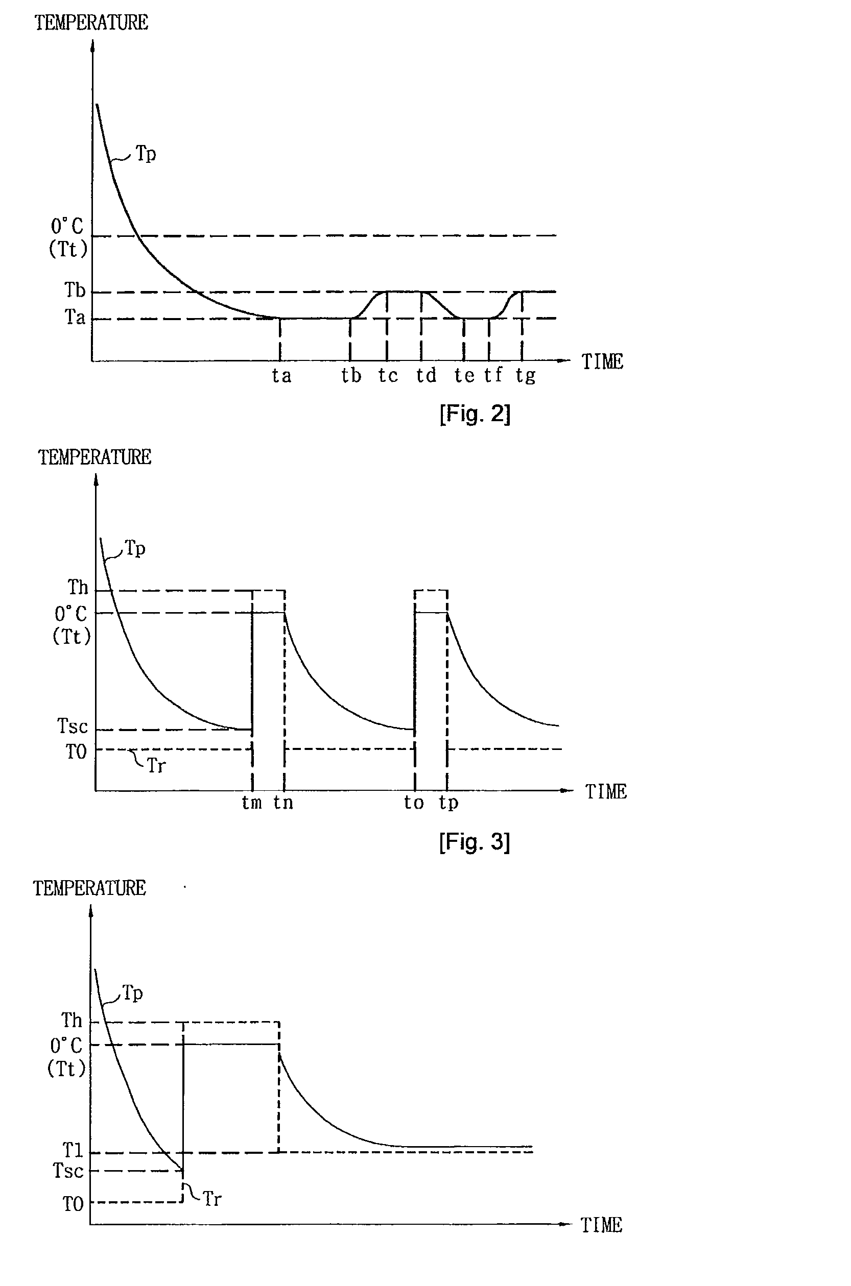
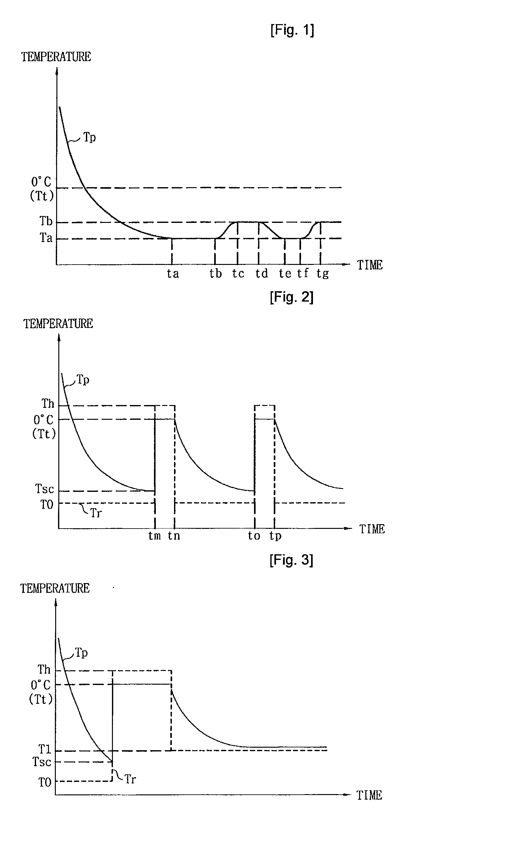
[0044]FIG. 1 is a graph showing temperatures in a supercooling method according to the present invention. Tp denotes a temperature of an object, Tt denotes a phase transition temperature of the object (0° C. in case of water) and Ta denotes a target temperature that is an optimum or stable supercooling temperature set according to information on the object (kind, mass, volume, etc.) or applicable to all objects. However, since the object may be released from a supercooled state at the target temperature Ta, the object is alternately supercooled at a temperature Tb higher than the target temperature Ta to be stably maintained in the supercooled state. Here, (Tb=Ta+ΔT). Tb represents a temperature of stably reliably maintaining the supercooled state, which is lower than the phase transition temperature Tt.
[0045]The object is cooled toward the target temperature Ta or the arbitrarily fixed target temperature Tb according to the information on the object (kind, mass, volume, etc.) by me...
third embodiment
[0052]In FIG. 3, a cooling temperature (or set temperature) Tr is fixed to a temperature T0 at an initial stage. The initial cooling temperature T0 may be variably set in association with at least one of a kind, mass and volume of an object. For example, the initial set temperature T0 may be differently set with respect to meat, vegetable, beverage, water, etc., and a cooling degree may be differently set according to the mass or volume. Particularly, in a case where information on the object does not exist, the entire objects are identically cooled at a preset temperature.
[0053]As the object is continuously cooled, a temperature Tp of the object becomes lower than a phase transition temperature Tt and is approximate to the cooling temperature Tr. Here, when the object maintained in the supercooled state is released from the supercooled state at Tsc, the temperature Tp of the object sharply rises to the phase transition temperature Tt. Whether the object is maintained in the superco...
fourth embodiment
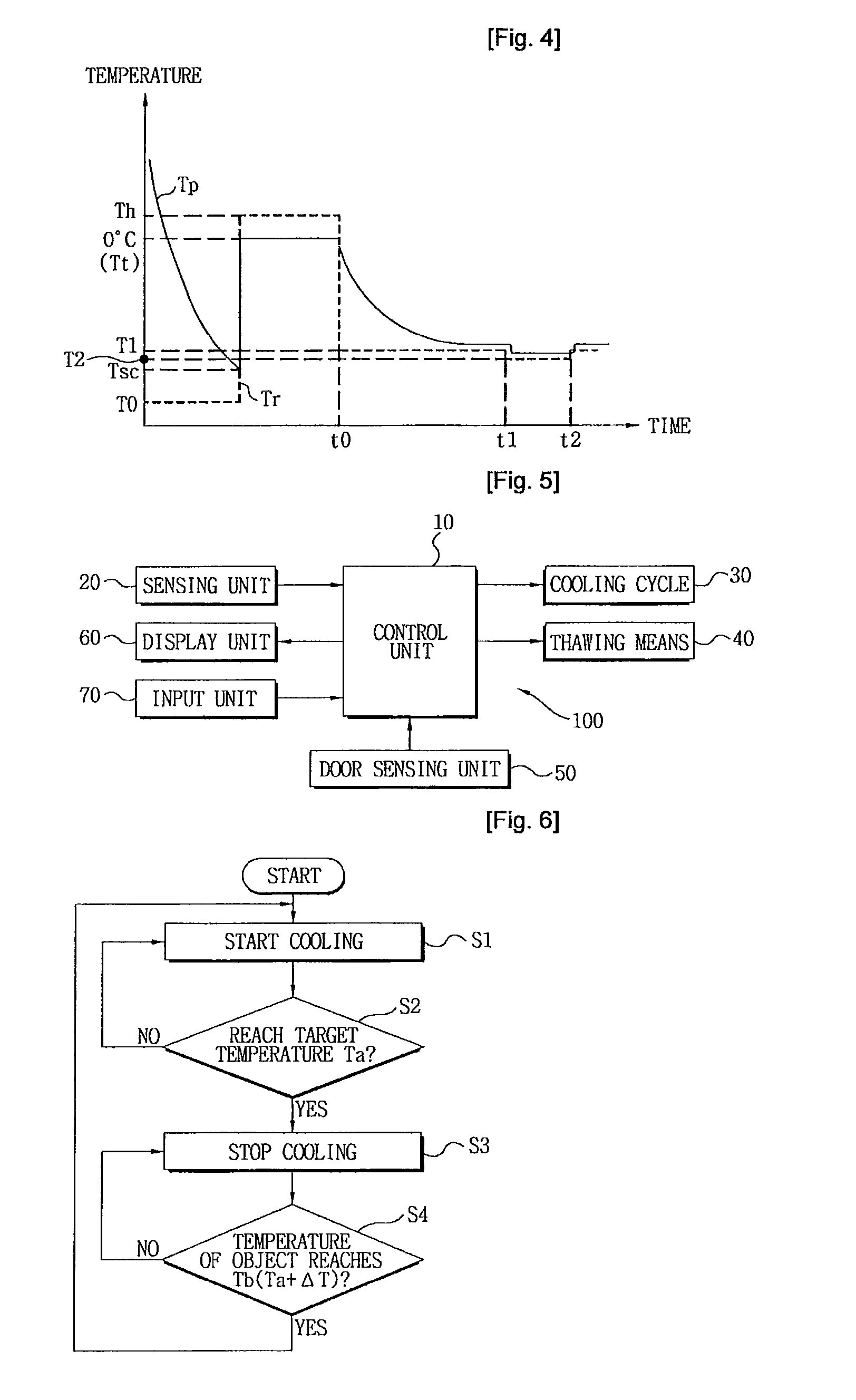
[0064]In FIG. 4, since a cooling temperature of cooling an object for the first time is T0, the object is released from a supercooled state, thawed, and cooled again as in FIG. 1. That is, a detected supercooling temperature of the object is a temperature T1.
[0065]Here, a temperature difference exists between the lowest temperature Tsc before the release of the supercooled state of the object and the temperature T1. In order to detect an optimum supercooling temperature of the object, cooling is performed toward a cooling temperature T2 between the lowest temperature Tsc and the temperature T1. That is, as shown in FIG. 4, in a case where the object is maintained in the supercooled state at the set cooling temperature T1 over a predetermined time, detected is the cooling temperature T2 of maintaining the object in the supercooled state, which is higher than the lowest temperature Tsc of the object before (directly before) the release of the supercooled state and lower than the tempe...
PUM
 Abstract
Description
Claims
Application Information