Crystal oscillator piece and method for manufacturing the same

a technology of crystal oscillator and manufacturing method, which is applied in the direction of piezoelectric/electrostrictive/magnetostrictive devices, electrical equipment, decorative arts, etc., can solve problems such as leakage vibration generation, and achieve the effect of reducing leakage vibration

Active Publication Date: 2010-08-12
CITIZEN WATCH CO LTD
View PDF5 Cites 9 Cited by
  • Summary
  • Abstract
  • Description
  • Claims
  • Application Information

AI Technical Summary

Benefits of technology

[0077]According to the crystal oscillator manufacturing method of the present invention, since the external shape is unaffected by the etching mask displacement, and the balance is adjusted by the balance adjusting groove substantially unaffected by the positional displacement, it becomes possible to achieve a crystal oscillator piece in which the leakage vibration is reduced to a negligibly small level.

Problems solved by technology

On the other hand, if the principal axis is tilted away from the X axis toward the Z′ axis, since the direction of the bending force does not coincide with the direction of the principal axis, oblique vibration containing a Z′ axis component occurs, resulting in the generation of leakage vibration.

Method used


Image

  • Crystal oscillator piece and method for manufacturing the same
  • Crystal oscillator piece and method for manufacturing the same
  • Crystal oscillator piece and method for manufacturing the same

Examples


Embodiment Construction

[0101]A crystal oscillator piece according to the present invention and a method for manufacturing the same will be described below with reference to the drawings. It should, however, be noted that the technical scope of the present invention is not limited to the specific embodiments described herein, but extends to the inventions described in the appended claims and their equivalents. The crystal oscillator piece according to the present invention is characterized by the cross-sectional shape of its vibrating tine; therefore, the following description deals mainly with the cross-sectional shape of the vibrating tine of the crystal oscillator piece.

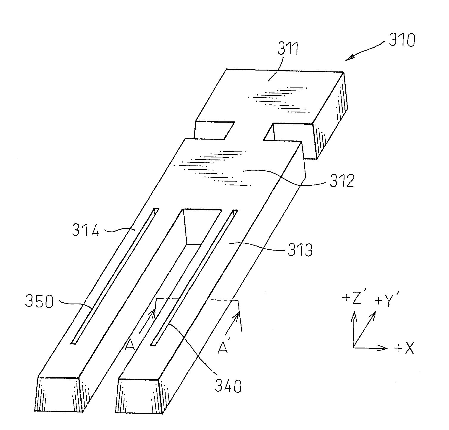
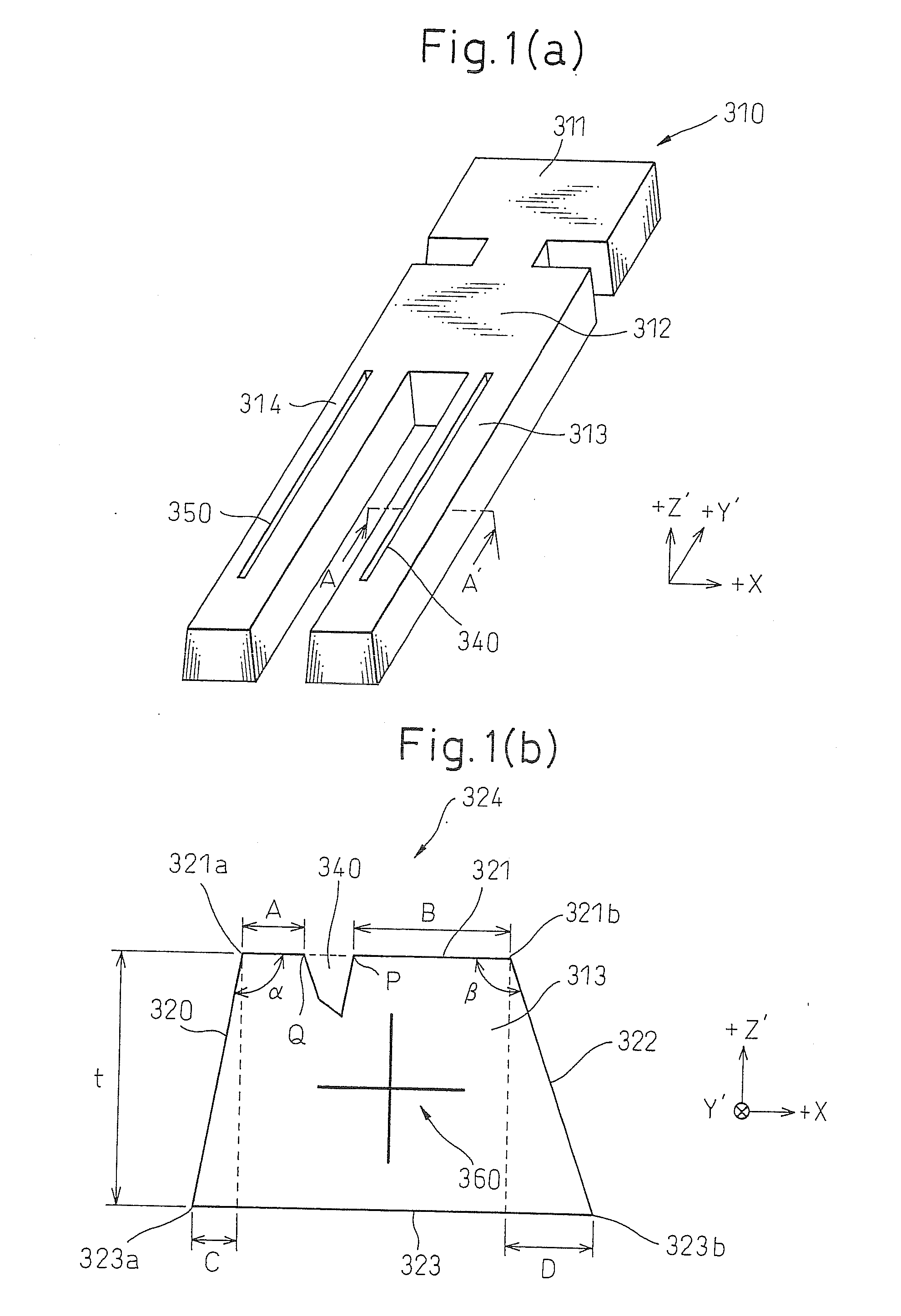
[0102]FIG. 1 is a diagram showing the crystal oscillator piece according to the present invention.

[0103]FIG. 1(a) shows a perspective view of the crystal oscillator, and FIG. 1(b) is an enlarged view of a cross section taken along line AA′ in FIG. 1(a).

[0104]As shown in FIG. 1(a), the crystal oscillator piece 310 according to the present...


PUM

PropertyMeasurementUnit
angleaaaaaaaaaa
angleaaaaaaaaaa
angleaaaaaaaaaa

Abstract

The present invention provides a crystal oscillator piece in which the cross section of its vibrating tine, while not symmetrical in shape, has a principal axis that is oriented parallel to an X axis to suppress the generation of leakage vibration, and a method for manufacturing such a crystal oscillator piece. More specifically, the invention provides a crystal oscillator piece includes a vibrating tine having an upper surface, a lower surface having a larger width than the upper surface, a first side face, and a second side face, and a balance adjusting groove formed in the vibrating tine, wherein the first and second side faces are formed in sloping fashion so that the width of the vibrating tine gradually increases from the upper surface toward the lower surface, and the balance adjusting groove is formed in accordance with the sloping of the first and second side faces so that at least one of two dynamically perpendicular principal axes passing through a centroid on a cross section taken perpendicularly to a longitudinal direction of the vibrating tine becomes substantially parallel to the upper surface or the lower surface. The invention also provides a method for manufacturing such a crystal oscillator piece.

Description

FIELD OF THE INVENTION[0001]The present invention relates to a crystal oscillator piece and a method for manufacturing the same, and more particularly to a crystal oscillator piece that has a structure for suppressing the occurrence of leakage vibration known as out-of-plane vibration, and a method for manufacturing such a crystal oscillator piece.BACKGROUND OF THE INVENTION[0002]A tuning fork crystal oscillator used for a vibratory gyro, etc., is manufactured by the steps including cutting a crystal oscillator piece of a desired shape from a crystal wafer, forming electrodes for causing the crystal oscillator piece to oscillate, and packaging the crystal oscillator piece with the electrodes formed thereon into a container. In particular, the step of cutting the crystal oscillator piece from a crystal wafer is an important step because the shape of the crystal oscillator piece determines the frequency of vibration and greatly affects the device performance.[0003]FIG. 15 is a diagram...

Claims


Application Information

Patent Timeline
Patent Type & Authority Applications(United States)
IPC IPC(8): H01L41/22H03H3/02H01L41/332
CPCH03H3/02H03H9/02086Y10T29/42H03H2003/026H03H9/21
Inventor KATOH, AKIKO
Owner CITIZEN WATCH CO LTD
Why Eureka
Try Eureka